
Victron Multiplus 3000 Inverter Charger Wiring Diagram
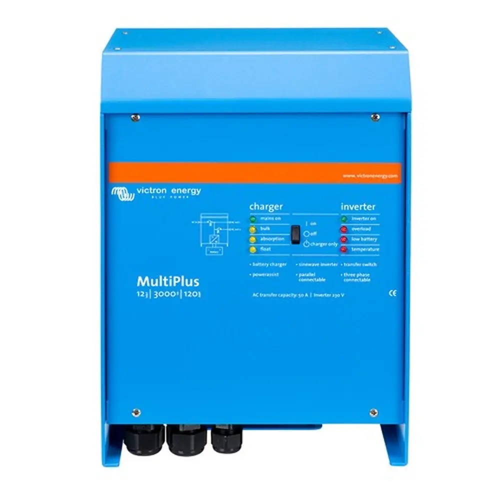
Victron Multiplus 3000 Inverter Charger Wiring Diagram
Power connections
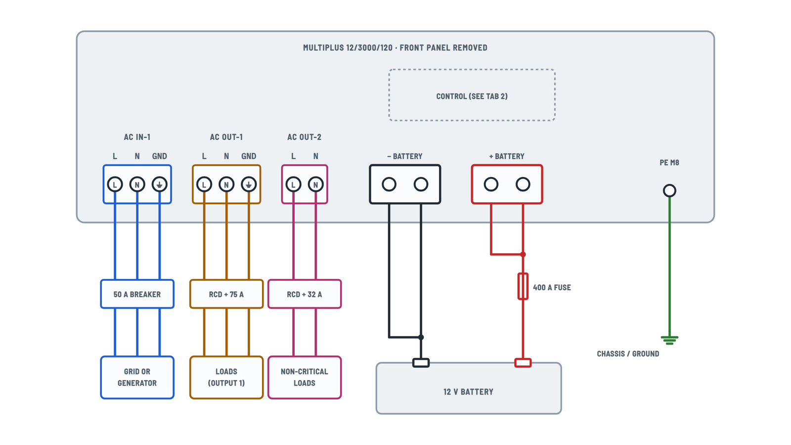
AC, battery and ground terminals, as on the unit's board.
Terminals and components · 6
- AC IN-1
- AC OUT-1
- AC OUT-2
- Ground
- Battery +
- Battery −
How to connect it
Three-conductor cable. Torque: 1.6 Nm. Protect it with a fuse or magnetic breaker rated 50 A max (lower if the supply is smaller).
Check
The appendix and its drawing show the terminals as L, N, ground (left to right), but the installation text says ground, N, L. Go by the labels printed next to the terminal block.
How to connect it
Put an earth leakage breaker and a fuse or breaker sized for the load (75 A max) in series.
PowerAssist
The inverter can add up to 25 A to the 50 A input.
Check
The appendix and its drawing show the terminals as L, N, ground (left to right), but the installation text says ground, N, L. Go by the labels printed next to the terminal block.
What it's for
For an electric water heater or air conditioner that should only run on grid or generator.
How to connect it
Put an earth leakage breaker and a fuse rated 32 A max in series. Its loads count toward the PowerControl / PowerAssist limit.
Depending on the installation
- Fixed: ground can come through the AC input cable; otherwise ground the case.
- Mobile (shore plug): connect the case to the vehicle chassis or to the boat hull or ground plate.
Boats
Direct connection to shore ground is not recommended because of galvanic corrosion: use an isolation transformer.
How to connect it
- Remove the four front screws and the front panel.
- Tighten the nuts to 12 Nm with an insulated wrench.
Data
Item Value Battery 400 - 1200 Ah DC fuse 400 A Caution
Avoid shorting the battery cables. Do not run them in closed conduit.
Starter battery
The starter battery negative is taken from this negative cable.
Control and signal terminals
Terminal strip E, remote H, alarm contact and VE.Bus.
Terminals and components · 9
- Temperature
- Voltage
- Remote
- Alarm
- VE.Bus
In parallel
One sensor per system is enough; with several (max one per unit), the highest reading wins.
Only one remote
Use either a switch or a Multi Control panel, not both.
Rating
AC: 120 V / 4 A. DC: 4 A up to 35 V DC, 1 A up to 60 V DC.
In parallel
Up to six identical units, with DC cables of equal length and size, and UTP cables run directly unit to unit, no splitter boxes.
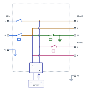
Internal block diagram
How the input, both outputs and the battery connect inside.
Terminals and components · 5
About This Diagram
This diagram is redrawn from the Victron Multiplus 3000 Inverter Charger manual, and we offer it completely free and in English. We have also categorized it in the Inverters (Solar & Batteries) section on Diagramverse, and it has been rated by 1 user with an average rating of 5.0. If you have any specific questions about the Victron Multiplus 3000 Inverter Charger Wiring Diagram, we suggest checking the Frequently Asked Questions (FAQs) section.
Printable Victron Multiplus 3000 Wiring Diagrams


Wiring Instructions
Before you start
Choose the Victron Multiplus 3000 tab that matches the job. The Complete tab covers the heavy wiring: AC IN-1, AC OUT-1, AC OUT-2, the primary ground and the doubled battery cables. The Control tab covers the sensor, relay, remote and data terminals. The Block diagram tab explains how the input relay, the output 2 relay and the ground relay behave. Check the rating label for your model. The 12/3000/120 needs a 12 V battery bank and the 24/3000/70 needs a 24 V bank. Both deliver 120 VAC at 60 Hz.
- Tools: insulated hand tools, a torque wrench for the M8 battery studs, a crimper sized for large battery lugs, a true-RMS multimeter and a DC clamp meter.
- Battery cables: two positive and two negative cables. Use 2 × 50 mm² for runs up to 16 ft and 2 × 70 mm² for 16 to 33 ft. Fit a 400 A DC fuse in the positive, close to the battery.
- AC wiring: the AC screw terminals take conductors up to 6 AWG (13 mm²). Feed AC IN-1 through a breaker of 50 A or less. Size every AC conductor for its breaker and for your local electrical code.
- Control wiring: 0.75 mm² wire for V-sense, and straight-through UTP cables with RJ45 plugs for VE.Bus.
- Location: a dry, dust-free, well-ventilated place with no textiles, plastics or chemicals nearby. The unit weighs about 19 kg (40 lbs), so get help to lift it.
- Permits: wiring into a building's electrical panel, a boat or an RV shore-power system usually requires a licensed electrician and, in many areas, a permit and inspection. Check local rules before you start.
Step-by-step wiring
- Mount the unit with the front switch set to off. Leave clearance around it for airflow.
- Open the AC supply breaker and lock it out. Remove the battery fuse, or leave it out if it isn't fitted yet. Remove the front panel only after both AC and battery are disconnected.
- Connect the Primary ground PE M8 stud to the vehicle chassis, hull ground or building grounding system. Do this before anything else and keep it permanent.
- Crimp lugs onto all four battery cables. Bolt both cables to the + M8 ×2 studs and both to the − M8 ×2 studs, and tighten them to 12 Nm. The two cables of each pole should be the same length and cross-section, so they share the current evenly.
- Run the cables to the battery with the 400 A fuse holder in the positive line. Connect the battery end, but don't fit the fuse yet.
- Fit the Temperature sensor on the battery negative post and plug it into TEMP + −.
- Run the V-sense + − wires (0.75 mm²) to the battery terminals or the DC bus, and check the polarity. In a parallel system, wire V-sense only on the master unit.
- If you have a starter battery, connect its positive to Starter +. Its negative goes to the battery negative cable.
- Wire the critical loads to AC OUT-1 (L, N and ground). Do not add a neutral-to-ground bond in the downstream panel. The internal ground relay makes that bond when the unit runs on battery and opens it when AC input is accepted.
- Wire the non-critical loads, such as a water heater, to AC OUT-2 (L and N). This block has no ground terminal. As general good practice, run those circuits' ground conductor from the unit's ground point or the ground bus.
- Wire AC IN-1 (L, N and ground) last, from a breaker that is still open.
- Connect the optional items: K1 · K2 or the Alarm contact for generator start or alarms, AUX 1 · AUX 2 for a lithium BMS, the H connector for a remote switch, and VE.Bus for a panel or for parallel units. Leave SW1 off unless you fit an external ground relay.
- Tug-test every terminal, then refit the front panel.
Testing and start-up
- Before you fit the fuse, measure the voltage at the battery and check its polarity. It must be within 9.5 to 17 V for the 12 V model or 19 to 33 V for the 24 V model. Then fit the 400 A fuse.
- Switch the unit to on with no AC applied. The "inverter on" LED should light. AC OUT-1 should read 120 VAC ±2% between L and N, and close to 0 V between N and ground. AC OUT-2 should be dead.
- Close the AC IN-1 breaker. The input must read 95 to 140 VAC and 45 to 65 Hz. Within a short time "mains on" should light and the charger should show bulk, absorption or float. AC OUT-2 comes on about 2 minutes later.
- With the charger running, measure the battery voltage at the battery posts and at the unit's studs. A large difference points to undersized or loose cables. The default absorption voltage is 14.4 V (12 V model) or 28.8 V (24 V model), and the default float voltage is 13.8 V or 27.6 V.
- Open the input breaker. Loads on AC OUT-1 should keep running without interruption, and AC OUT-2 should switch off.
- Re-check the battery stud torque after the first few days, then check all connections once a year.
Safety notes
- The battery is a permanent energy source. The AC terminals can carry dangerous voltage even when the switch is off. Disconnect both AC and battery before you work on the unit.
- A battery bank can deliver an enormous short-circuit current. Take off rings and watches, cover any terminal you are not working on, and never let a wrench bridge the battery posts.
- Never replace the 400 A fuse or the input breaker with a different type or rating.
- Equalization raises the charge voltage. Disconnect DC loads before you run it.
- Keep relay loads within the contact ratings: 120 V / 4 A AC, or 4 A up to 35 V DC.
Troubleshooting
| Symptom | Probable Cause | What to Check |
|---|---|---|
| Nothing happens when I switch the unit on; no LEDs and no inverter output | No DC voltage at the unit: blown or missing 400 A fuse, loose battery lug, or battery voltage out of range | Measure voltage directly on the + M8 and − M8 studs. It must be 9.5-17 V (12 V model) or 19-33 V (24 V model). Check the fuse for continuity and the lugs for 12 Nm torque. |
| Inverter shuts down when big loads start, with "low battery" and "overload" flashing together | Excess ripple on the DC connection (over 1.5 Vrms), caused by undersized, overlong or loose battery cables, or a battery bank that is too small | Confirm you have two cables per pole at 2 × 50 mm² up to 16 ft or 2 × 70 mm² up to 33 ft. Measure the voltage drop between battery posts and studs under load, and re-torque all lugs. |
| Generator or grid is connected but "mains on" never lights and the battery doesn't charge | Input voltage or frequency outside the accepted range, AC IN-1 breaker open, or a distorted generator waveform | Measure at AC IN-1 L-N: it should be 95-140 VAC at 45-65 Hz. Check the input breaker. With a generator, enable the WeakAC and dynamic current limiter settings. |
| Input breaker or generator trips as soon as the charger starts | Charger demand plus loads exceed the supply, or the input current limit is set too high | Set the AC input current limit to match the breaker or generator (PowerControl). Check for a short or overload on AC OUT-1 or AC OUT-2, then reset the breaker. |
| Loads on the second output have no power | The unit is in inverter mode, AC has only just returned, or the loads are on the wrong output | AC OUT-2 is live only with accepted AC on the input and comes back about 2 minutes after AC returns. Move loads that must run on battery to AC OUT-1. |
| "Bulk" and "absorption" LEDs flash at the same time | Voltage sense error: the reading at V-sense differs by more than 7 V from the battery studs | Check that the V-sense + − wires go to the correct battery poles, aren't reversed, and are intact and tight. |
| "Absorption" and "float" LEDs flash at the same time | Temperature sensor reading is implausible: the sensor is loose, miswired or faulty | Make sure the sensor is bolted to the battery negative post and fully plugged into TEMP + −. Replace it if the error persists. |
| Charge current drops to zero as soon as absorption begins | Battery over 50°C, or a defective temperature sensor | Check the battery temperature and ventilation. Unplug the sensor. If charging resumes normally after about 1 minute, replace the sensor. |
| GFCI or RCD on the output doesn't trip, or trips at random, on inverter power | Extra neutral-to-ground bond in the downstream panel, or SW1 set to external with no external ground relay fitted | On battery operation, measure N to ground at AC OUT-1: it should read close to 0 V. Remove any downstream bond. Leave SW1 off unless an external relay is wired to GND relay. |
| Starter battery never charges | Starter battery negative not tied to the house battery negative, or a loose wire on Starter + | Measure voltage between Starter + and the starter battery negative. Connect that negative to the house battery negative cable. Remember that this output is limited to 4 A. |
| Batteries ran flat during a grid outage although I only wanted charging | Unit or remote switch left on "on" instead of "charger only" | Set the front switch to "charger only", or wire the H connector with right and middle shorted. The front switch must also be set to "on" for the remote to control the unit. |
| Parallel or three-phase units won't start, and the LEDs show a VE.Bus code | Wrong or faulty VE.Bus cable, or units missing from the configuration | Use straight-through UTP cables between the VE.Bus RJ45 connectors. Check each plug, then switch all units off and on again. |