
EZGO 36v 1996 Golf Cart Wiring Diagram
Drive wiring schematic
Batteries, solenoid, direction selector, pedal box, 1206 controller and motor.
Terminals and components · 11
- Batteries
- Charger
- Solenoid
- MS2
- Key
- MS3
- ITS
- Reverse
- Selector
- Motor
- Controller
Power cables
The heavy lines in the manual are the power harness: batteries, solenoid, selector, motor and controller. The rest is control wiring.
Before working
Disconnect the pack negative (BL−) first and reconnect it last.
Parts
Part Function Contact Joins the pack to the controller when the pedal is pressed 250 Ω 5 W Across the two large solenoid terminals Coil Red (RED) from MS3; black (BLK) to B− Diode In parallel with the coil Diode polarity
Check that the diode's band faces the coil's red (+) wire, as in the schematic.
Wire colors
Code Color BLU Blue GRN Green RED Red WHT White BLK Black ORN Orange Terminals
Terminal Goes to A Controller B+ B Motor field S2 C Controller A2 and motor A2 D Motor field S1 Terminals
Terminal Wire B+ Solenoid (controller side) and selector terminal A B− BL−, charger − and solenoid coil M− Motor A1 A2 Selector terminal C 1 · 2 Throttle sensor (WHT, BLK) 3 MS4, reverse (ORN) 4 MS3, pedal (RED)
Accessory wiring
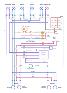
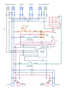
Lights, turn signals, brake light, horn and state-of-charge meter, on 12 V taken from the pack.
Terminals and components · 9
- +12 V
- Fuses
- Lights
- Horn
- Brake
- Flasher
- Turn
- Meter
- Ground
Caution
Do not connect 12 V accessories to any other point of the pack: they would get 24 or 36 V.
Outputs
Fuse Wire and circuit 1 ORN/WHT: horn button 2 RED: brake switch and flasher 3 BLU/WHT: light switch Without turn signals
Remove the white wire (WHT) from the left taillight and the yellow wire (YEL) from the right one, and connect the brown wire (BRN) to each taillight's red lead.
Wires
Wire Goes to GRN Right front turn lamp RED Left front turn lamp BRN Brake switch WHT Left taillight (turn and brake) YEL Right taillight (turn and brake) Splices
The dots in the diagram are splices inside the harness.
About This Diagram
These diagrams are redrawn from pages 184–185 of the EZGO 36v 1996 Golf Cart manual, and we offer them completely free and in English. We have also categorized it in the Golf Carts (Powersports) section on Diagramverse, and it has been rated by 1 user with an average rating of 5.0. If you have any specific questions about the EZGO 36v 1996 Golf Cart Wiring Diagram, we suggest checking the Frequently Asked Questions (FAQs) section.
Printable EZGO 36v 1996 Wiring Diagrams



Wiring Instructions
Before you start
First, pick the EZGO 36v 1996 tab that matches the job. The Drive tab covers the 36 V traction circuit: battery pack, Main solenoid, MS2, MS3, MS4, the throttle sensor (ITS), the direction selector and the 1206 controller. The Accessories tab covers the 12 V lights, horn, brake light, turn signals and State of charge meter. On the Accessories tab, choose With turn signals if your cart has a flasher and a turn signal switch on the steering column. Choose Without turn signals if your brake light is wired straight to the taillights.
E-Z-GO built several electrically different 1996 cars. DCS models, Freedom models with the HD speed control, and early versus mid-1996 production all use different speed control assemblies, harnesses or pedal-box microswitches. Before you trust the drawing, compare your controller, solenoid and harness labels with it. If they don't match, check the serial number plate and ask an E-Z-GO parts source what your vehicle uses.
Tools: a digital multimeter, a crimping tool, insulated sockets and wrenches, a battery terminal brush, heat-shrink or vinyl tape, nylon clamps, and safety glasses and gloves. A clamp-on current indicator helps when you diagnose high-current faults.
Wire gauge: no gauges are given for this cart. Replace each power cable (battery jumpers, solenoid-to-B+, motor and selector cables) with one of the same size or heavier, with crimped, sealed lugs. Never swap a heavy cable for a lighter one. Control and accessory wires can be replaced like for like, keeping the original color so the circuit stays traceable.
Power isolation: remove the key, set the direction selector to neutral, set the park brake, and disconnect the pack negative before you touch any power cable. Unplug the charger. No permit is involved, but if you aren't comfortable working on a high-current DC pack, have a golf cart technician do the work.
Step-by-step wiring
- Battery pack: mount the six 6 V batteries and connect them in series, positive of one to negative of the next. That leaves one free BL+ and one free BL−. Clean every post and lug until bright, and tighten firmly. A loose jumper is the most common source of heat and voltage drop.
- Main power path: run BL+ to the battery-side terminal of the Main solenoid. Then run the solenoid's other contact terminal to controller B+. Leave BL− for last.
- Solenoid parts: fit the 250 Ω 5 W resistor across the solenoid contacts and the diode across the coil. The silver band on the diode must face the same way as in the original installation. A reversed diode shorts the coil supply.
- Charger connector: connect + to the battery-side solenoid terminal (together with BL+) and − to controller B−.
- Direction selector and motor: connect selector contact A to B+, C to motor A2, B to S2 and D to S1. Connect motor A1 to controller M−. Make sure the series field (S1/S2) goes through the selector and the armature does not. Otherwise the cart won't reverse properly.
- Control chain: wire MS2 (in the selector) so its blue wire goes to the key switch BLU input. Run the key switch GRN output to MS3 in the pedal box. Run the MS3 RED output to controller pin 4 and to the solenoid coil.
- Throttle sensor: connect the ITS white wire to pin 1 and its black wire to pin 2. Leave pins 5 and 6 empty.
- Reverse circuit: connect MS4 so its orange wire feeds pin 3 and the reverse buzzer. MS4 must close only in reverse.
- Accessories: take the +12 V green feed from the two batteries shown on the Accessories tab, never from the full pack. Feed the fuse block, which holds three 15 A fuses for the horn, brake/turn signals and lights. Then wire the light switch (BLU/WHT), horn button (ORN/WHT to YEL), brake switch (RED to C, NO to BRN), flasher and turn signal switch. Bring every black return to the common accessory ground at the pack negative.
- No turn signals: if your cart has no turn signals, remove the WHT wire from the left lamp and the YEL wire from the right lamp, and connect BRN to RED, so the brake switch lights the taillights directly.
- State of charge meter: connect red to the 36 V positive and black to ground.
- Finish: clamp all harnesses away from sharp edges, the motor and moving linkage. Then reconnect the pack negative last.
Testing and start-up
Raise the rear wheels and support the cart on safety stands on firm, level ground. Never lift or support it on the rear axle differential casting. Chock the front wheels.
- Measure across BL+ and BL−. A healthy, charged pack reads about 36 V. Each battery should read about 6 V, and the readings should be close to each other.
- Measure the accessory +12 V green wire to ground. You should see about 12 V, not 36 V.
- With the key on and the selector in F, press the pedal. The Main solenoid should click and the wheels should turn slowly forward. Release the pedal and the solenoid should drop out.
- In neutral, pressing the pedal must do nothing: MS2 is open.
- In R, the buzzer must sound and the wheels must turn backward.
- Check the lights, horn and brake light, plus both turn signals if fitted. The State of charge meter should respond.
Safety notes
- A 36 V pack won't usually give you a dangerous shock, but it can deliver hundreds of amps into a short. A dropped wrench across a battery can weld, burn you or make a battery explode. Remove rings and watches, and use insulated tools.
- Batteries give off hydrogen when charging. Keep sparks and flames away, and work with good ventilation.
- Wear eye protection near flooded batteries. Do not overfill them.
- Never connect 12 V accessories across the full 36 V pack.
- Keep the drive wheels off the ground or the selector in neutral until every connection has been checked.
Troubleshooting
| Symptom | Probable Cause | What to Check |
|---|---|---|
| Nothing happens and the solenoid doesn't click when I press the pedal | Open control chain: MS2, the key switch, MS3 or a loose BLU/GRN/RED wire | Key on, selector in F, pedal pressed. Check for about 36 V on BLU at the key switch, then on GRN, then on RED at pin 4. Wherever the voltage disappears is where the fault is. |
| The solenoid clicks but the cart doesn't move | Loose or corroded power cable, worn solenoid contacts, or an open motor or selector connection | Measure voltage across the solenoid's large terminals with the pedal pressed. It should be close to 0 V. Then check B+, M−, A1, A2, S1, S2 and selector contacts A to D for tightness and heat discoloration. |
| The cart goes forward in R, or barely moves in one direction | Selector cables on the wrong contacts, or armature and field leads swapped | Verify A to B+, C to A2, B to S2, D to S1 and A1 to M−. In F, A–B and C–D should show continuity. In R, A–D and B–C should. |
| No reverse buzzer, or the cart runs badly only in reverse | MS4 not closing, or the orange wire not reaching pin 3 | In R with the key on, check for about 36 V on ORN at pin 3. With the selector in F or N, it must read 0 V. |
| Solenoid engages but there is no speed control, or the cart jumps to full speed | ITS wires reversed, loose or damaged | Confirm white is on pin 1 and black on pin 2, and that the pedal box connector is fully seated. Inspect the harness for chafing near the pedal linkage. |
| A fuse or wire burned out right after I replaced the solenoid | Coil diode installed backward, which shorts the coil feed | Check the orientation of the diode's silver band against the original layout. Replace any damaged wire and the diode if it failed. |
| Lights or horn burned out instantly, or bulbs blew | Accessories fed from 36 V instead of the 12 V tap | Measure the green +12 V feed to ground. It must read about 12 V. Move the tap to the correct two batteries and replace the damaged bulbs and fuses. |
| All accessories dead at once | Missing +12 V tap or a broken common BLK ground | Check for about 12 V at the fuse block input, then check continuity from the accessory BLK ground to the pack negative. |
| Brake lights don't work on a cart without turn signals | Wrong variant wiring: BRN still running to the absent turn signal switch | Remove WHT from the left lamp and YEL from the right lamp, and connect BRN to RED. With the brake pressed, BRN should show about 12 V. |
| Cart is sluggish, and cables or battery posts get hot | Loose or corroded battery jumpers, or an undersized replacement cable | Under load, measure each battery. A battery that drops far below the others, or a hot terminal, points to the bad connection. Clean it, retighten it, and use cable at least as heavy as the original. |
| Charger connects but the pack never charges | Charger connector leads open or not landed on the battery-side solenoid terminal and B− | With the charger unplugged, check continuity from the connector + to BL+ and from − to B−. Inspect the receptacle contacts for burning. |