
Honeywell Fan Limit Switch L4064B Wiring Diagram
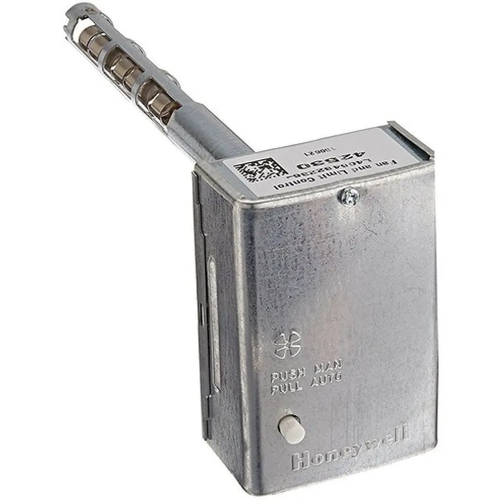
L4064B fan and limit control
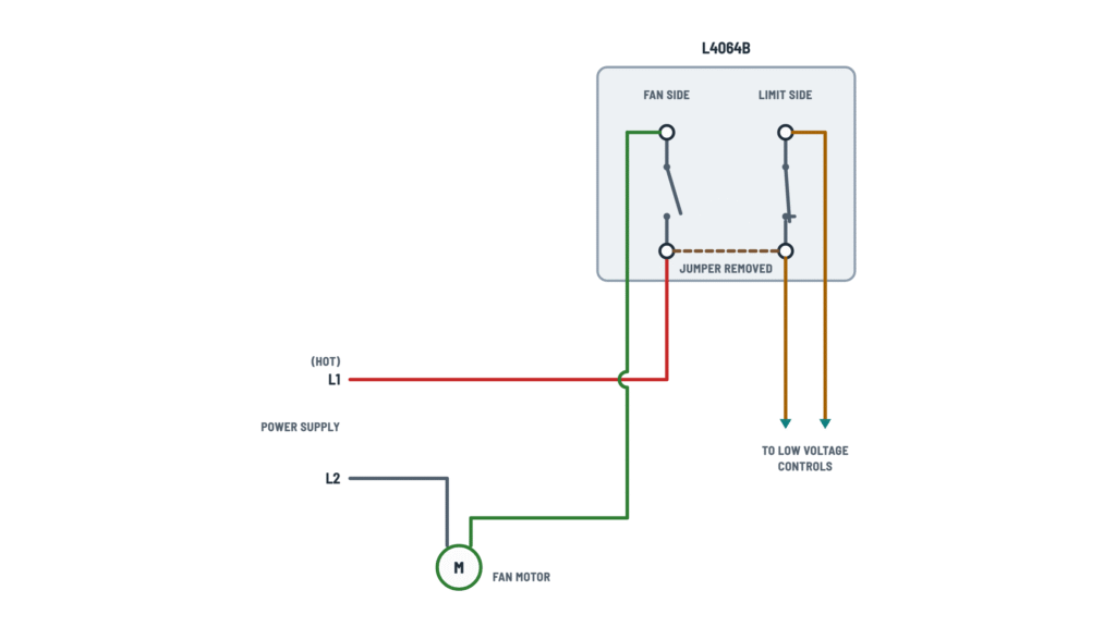
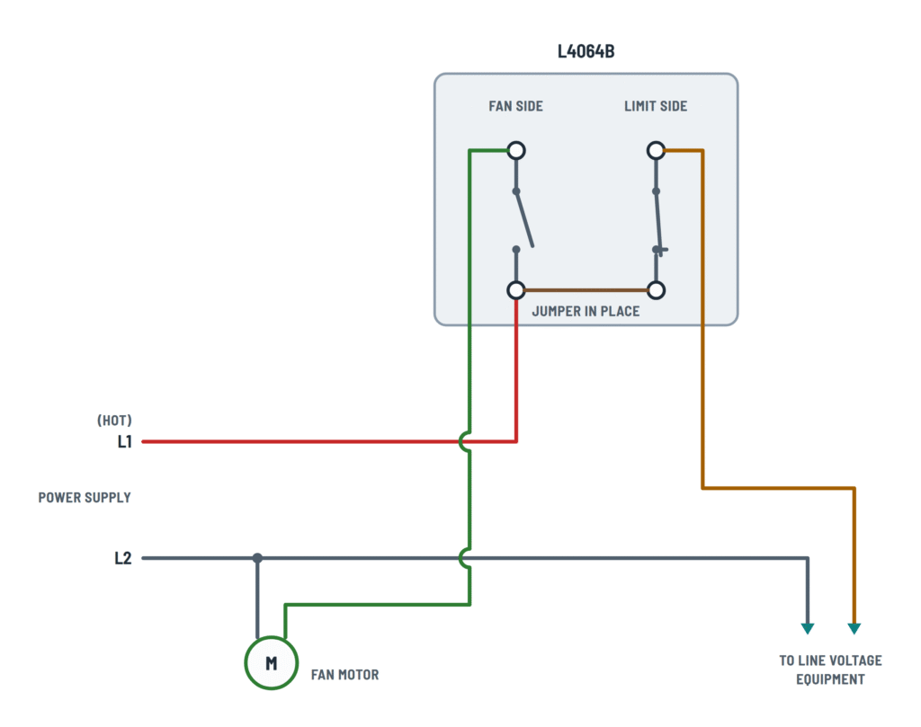
Three ways to wire the limit: low voltage or line voltage.
Terminals and components · 7
- L1 hot
- L2 neutral
- Fan
- Limit
- Jumper
- Controlled equipment
What it does
Feeds the fan motor through the fan contact.
Protection
Add a disconnect means and overload protection as required.
What it does
It enters at the fan's lower terminal; the jumper also passes it to the limit side.
Protection
Add a disconnect means and overload protection as required.
What it does
Without the jumper, the hot leg is wired to both lower terminals (fan and limit).
Protection
Add a disconnect means and overload protection as required.
What it does
Completes the 120 V circuit. It does not pass through the L4064B.
What it does
The bimetal element closes the contact as the plenum heats up and opens it as it cools, so it won't blow cold air.
Setting
- FAN ON lever: temperature at which it starts.
- FAN OFF lever: temperature at which it stops.
- Hold the dial while moving the levers.
Continuous fan
Front button: pushed in = fan always on (MAN); pulled out = automatic (AUTO).
Ratings
Maximum combined connected load: 2000 VA. Check the motor nameplate and the control ratings before wiring.
Checkout
When done, call for heat: the fan should start when the plenum reaches FAN ON.
What it does
The two limit terminals go in series with the burner's low voltage (24 V or millivolt) circuit.
Ratings
Pilot duty: 2 A at 24 V AC; 0.25 A at 0.25–12 V DC.
Setting
The LIMIT lever is factory-set at 200 °F (93 °C). The limit stop must not be altered by the homeowner.
What it does
It stays closed in normal operation; if the plenum overheats, it opens and shuts off the burner.
Setting
The LIMIT lever is factory-set at 200 °F (93 °C). The limit stop must not be altered by the homeowner.
When to remove it
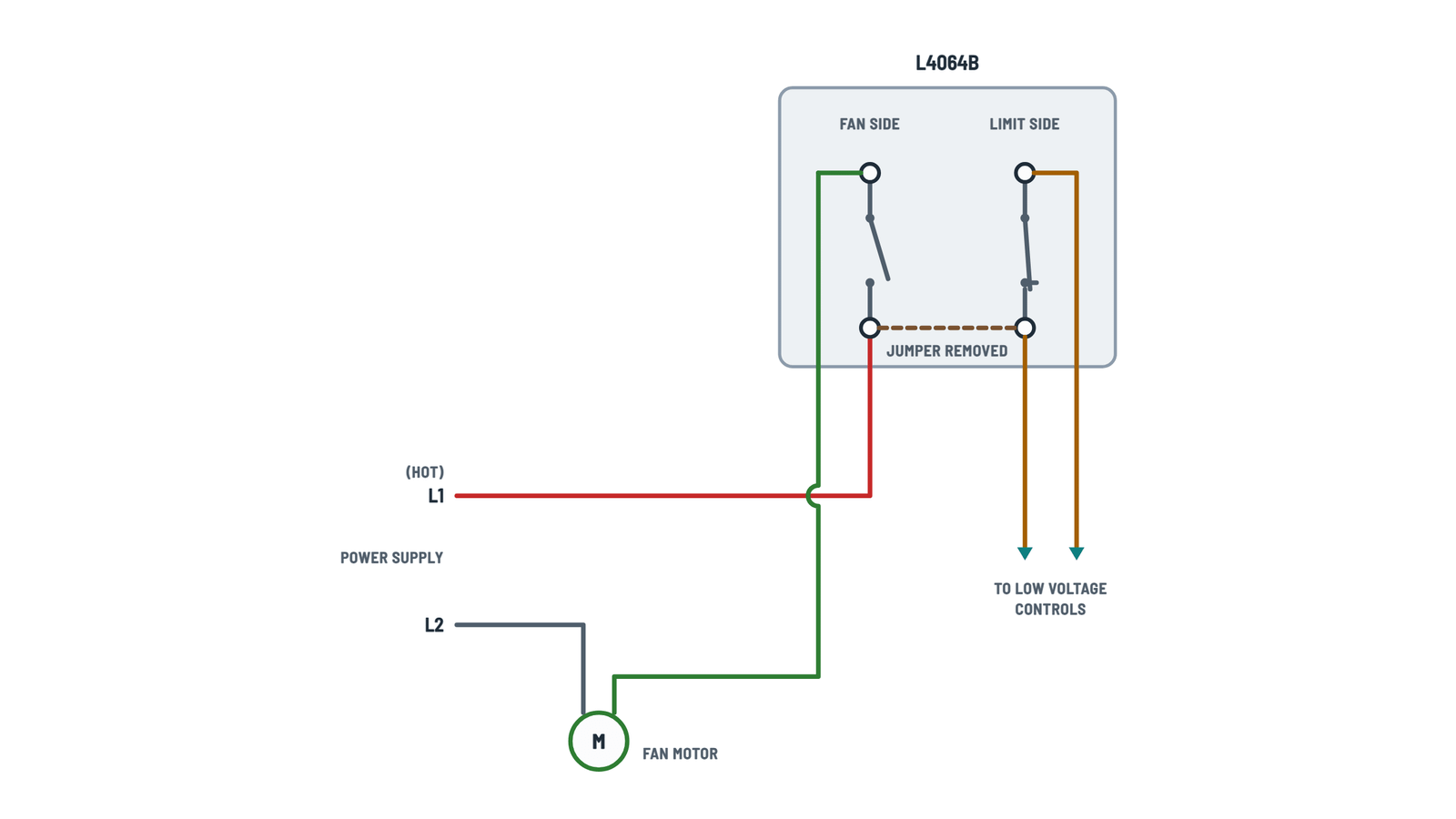
Whenever the limit is in a low voltage circuit. Break it off with needlenose pliers; it cannot be replaced.
Caution
If left in place, 120 V reaches the low voltage controls: risk of shock and damage.
When to keep it
When the limit and the fan share the same 120 V hot leg.
No jumper
The jumper is gone (or was removed): the hot leg is wired to both lower terminals.
How to connect it
The two limit wires are inserted into the burner's low voltage circuit (for example, the gas valve).
How to connect it
The limit's upper terminal supplies the hot leg to the line voltage equipment; its neutral goes to L2.
How to connect it
The limit feeds the 120 V primary of the heating transformer; the 24 V secondary goes to the low voltage controls.
About This Diagram
This diagram is redrawn from page 3 of the Honeywell Fan Limit Switch L4064B manual, and we offer it completely free and in English. We have also categorized it in the Fan & Blower Motors (HVAC & Water Heating) section on Diagramverse, and it has been rated by 1 user with an average rating of 5.0. If you have any specific questions about the Honeywell Fan Limit Switch L4064B Wiring Diagram, we suggest checking the Frequently Asked Questions (FAQs) section.
Printable Honeywell L4064B Wiring Diagrams


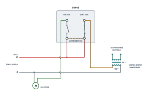
Wiring Instructions
Before you start
Pick the Honeywell L4064B variant that matches your furnace before you touch a wire. Use A · Low voltage when the limit opens a 24 V or millivolt gas valve circuit. Use B · Line, jumper in when the limit breaks the 120 V hot leg of line-voltage burner equipment fed from the same L1 as the fan. Use C · Line, no jumper when the limit breaks the 120 V primary of the 120/24 V heating system transformer and L1 goes to both lower terminals. If you are replacing an old control, label every existing wire before you remove it and copy that circuit.
This control should be installed by a trained, experienced service technician. Work on furnace safety controls may require a permit or a licensed professional where you live, so check locally. Wiring must follow your local codes. Where there are none, follow the National Electrical Code. The wiring must also meet NEC Class 1 requirements.
You need needlenose pliers, a small flat screwdriver, a wire stripper, a non-contact voltage tester and a multimeter. Use wire rated for at least 75 °C (167 °F): Nos. 14, 16 or 18 solid wire, or Nos. 14 or 16 stranded wire, sized for the load. For the female receptacles, use Nos. 14 to 18 wire with 1/4 in. (6.4 mm) male flag connectors. On 240 V applications you must use double insulated cable.
Turn off the furnace service switch and the breaker, then use a tester to confirm that L1 is dead. Check your loads against the ratings. At 120 Vac the fan side is rated 14 A full load (84 A locked rotor) and the limit side 8 A full load (48 A locked rotor). The maximum combined connected load is 2000 VA.
Step-by-step wiring
- Remove the cover. Pull the slotted knockout straight down with needlenose pliers. If you use cable, fit the strain relief bushing and pass the wires through it before connecting. Don't put strain on the control case.
- Deal with the Brass jumper. For variants A and C, break it off with needlenose pliers and remove it completely. It cannot be replaced, so be sure before you break it. For variant B, leave it in place.
- Strip each wire to the length shown on the strip gauge on the controller. If the insulation is about 2 mm thick, strip an extra 1/4 in. (6 mm) so the wire seats fully.
- Connect L1: 120 V hot to the lower terminal of the Fan side. In variant C, also run L1 to the lower terminal of the Limit side. Push solid wire straight into the hole. For stranded wire, hold a small screwdriver in the slot beside the terminal while you insert the wire.
- Connect the upper Fan side terminal to the Fan motor, and connect the motor's other lead to L2: neutral.
- Wire the Limit side. Variant A: put the limit in series with the 24 V or mV control circuit. Variant B: run the upper limit terminal to the hot lead of the 120 V equipment, and connect the equipment's return to L2. Variant C: run the upper limit terminal to the transformer primary, and connect the other primary lead to L2.
- Wire accessories such as an electronic air cleaner or humidifier to the female receptacles. Push each flag connector to the bottom of the cavity, with the wire lying in the channel.
- Tug every wire to confirm it is locked in. Route all wires clear of the rotating scaleplate, then close the strain relief bushing.
Testing and start-up
Hold the scaleplate dial while you set the levers so it can't turn and strain the element. Set LIMIT to the furnace manufacturer's value (factory-set at 200 °F). Set FAN ON to the temperature where warm air should start and FAN OFF to the temperature where the fan should stop before it blows cool air. Pull the FAN button out for automatic cycling.
Check the limit first. With the power off, disconnect the fan motor circuit at the control. Restore power and call for heat. The burner should light, and the limit should shut it off when the plenum reaches the limit setting. Turn the power off, reconnect the fan, restore power and call for heat again. The fan should start at the FAN ON setting. It should stop after the call for heat ends and the plenum cools to FAN OFF.
With a multimeter, you should read about 120 V between L1 and L2. You should read the same voltage across the fan motor when the fan contact closes. In variant A, closed limit contacts read near 0 V, and open contacts read roughly the 24 V control voltage.
Safety notes
- The fan side carries 120 V even when the burner is off. Disconnect power before you open the cover.
- Never leave the brass jumper in place when the limit is in a low voltage circuit. It puts line voltage on the 24 V controls, which creates a shock hazard and damages them.
- The limit is a safety device. Never bypass it, and never set the limit stop higher than the equipment manufacturer's setting.
- On bracket mounting, the setscrew must strike the tube frame, never the sensing element. Otherwise the limit function can be bypassed.
- Keep the switch below 190 °F (88 °C). Add insulation or use a bracket if the plenum surface runs hotter.
- Stay within the pilot duty ratings: 2 A at 24 Vac, and 0.25 A at 0.25 to 12 Vdc.
Troubleshooting
| Symptom | Probable Cause | What to Check |
|---|---|---|
| The thermostat, transformer or gas valve burned out as soon as power was turned on | The brass jumper was left in place with the limit in a low voltage circuit, so 120 V reached the 24 V controls | With power off, check whether the jumper between the lower terminals is still there. For variant A it must be broken off completely. Replace the damaged low voltage parts before you restore power. |
| The burner never lights after I replaced the control | The jumper was removed in a variant B installation, so the limit side has no hot feed | Measure from the lower Limit side terminal to L2. You should read 120 V. If you read 0 V, add a separate L1 lead to that terminal and wire it as variant C, because the jumper cannot be replaced. |
| The fan never comes on, but the burner works | L1 is not on the lower Fan side terminal, or a push-in wire is not seated | With the furnace hot, measure L1 to L2 at the lower fan terminal (about 120 V), then measure across the motor leads. Strip the wire to the strip gauge length and reinsert it. |
| The fan runs all the time and never stops | The FAN button is pushed in (manual), or the motor is fed directly from L1 instead of through the fan contact | Pull the FAN button out to AUTO. Confirm that the motor hot lead lands on the upper Fan side terminal, not on L1. |
| The burner keeps cycling off on the limit and the plenum gets very hot | The fan is wired to the wrong terminal or isn't running, so heat isn't removed from the plenum | Do the checkout with the fan connected. The fan should start at FAN ON. Check the motor wiring to L2 and the voltage at the upper fan terminal. |
| A breaker trips or the contacts look burned and pitted | The load exceeds the ratings, or the wire is undersized | Compare the motor nameplate with 14 A full load (fan) and 8 A full load (limit) at 120 Vac, and keep the total under 2000 VA. Use No. 14 to 18 wire rated 75 °C or higher, sized for the load. |
| The furnace works on and off and a wire feels loose | Stranded wire not fully seated in a push-in terminal, or a flag connector not pushed to the bottom of the cavity | With power off, tug each wire. Reinsert stranded wire while you hold the release slot open with a screwdriver, and push the spades fully home. |
| The settings drift or a lever won't stay put | A wire is touching the rotating scaleplate, or the dial was turned while you set the levers | Reroute the wires clear of the scaleplate. Hold the dial while you move the levers and recheck the FAN and LIMIT settings. |
| The limit never opens even when the plenum overheats | The bracket setscrew is pinching the sensing element, or the limit side is bypassed in the wiring | Make sure the setscrew bears on the tube frame or bushing. Confirm that the controlled equipment's hot lead, or the 24 V circuit, actually passes through the Limit side contacts. |