
Bulldog Security Deluxe 500 Wiring Diagram
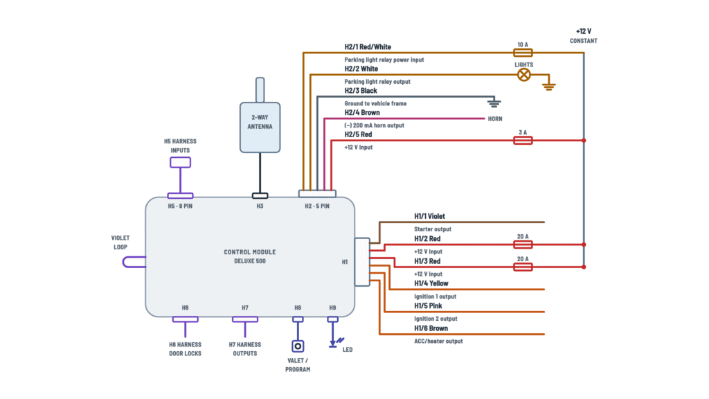
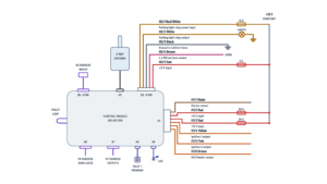
Installation diagram
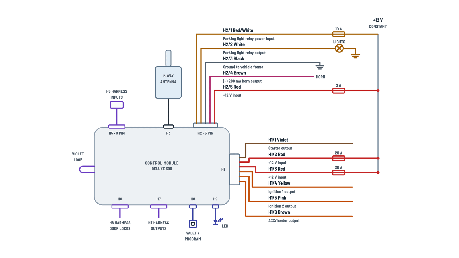
The module and its connectors: power (H1), lights, horn and supply (H2), antenna and harnesses.
Terminals and components · 17
- +12 V
- Ground
- Ignition and accessory
- Starter
- Parking lights
- Horn
- Harnesses and loop
- Valet and LED
How to find it
With a multimeter: 12 V with the key in «Start» and 0 V in every other position.
Safety
On automatics, the starter circuit must go through the neutral safety switch, closed in Park or Neutral only.
Fuses
Remove both 20 A fuses before connecting these wires and do not reinstall them until the harness is plugged into the module.
Two power feeds
If the ignition switch has two separate +12 V feeds, connect one red wire to each.
Required
The yellow wire must always be connected.
Not used
If not needed, cap or tape the end of the wire.
Two accessory wires
Some vehicles (e.g., Ford) have one wire for the blower and another for the AC: add a relay, or use the pink (H1/5) if there is no ignition 2.
Lights switched to ground (−)
Cut the red/white from the red wire and connect it to ground. Tape the red wire at the cut.
Current
If the lights draw more than 10 A, add a relay.
Connection
Use solid, clean frame metal.
Caution
It is a low-current transistor output: only to the low-current ground wire from the horn switch.
Constant
It must have 12 V at all times, in any key position.
Mounting
- It must not block the driver's view.
- Clean the glass before removing the protective tape.
- Route the black cable behind the trim to the module.
Range
Some tinted windows can greatly reduce the range.
Connector
9-pin black connector for the inputs.
Connector
6-pin white connector for the doors.
Connector
10-pin white connector for the outputs.
Mounting
Pick a hidden spot reachable from the driver's seat and plug the wire into the module.
Mounting
Drill a 6 mm hole with at least 6 mm clear behind it and press the LED in.
Manual transmission
- Also connect the brown/red (H5/2) to the handbrake and brake light circuits, with isolation diodes.
- Connect a door input: green (H5/6) or violet (H5/7).
- Use the tach or oil sensor engine checking mode.
Caution
Not recommended on manual transmission vehicles with removable tops.
H5 harness: inputs
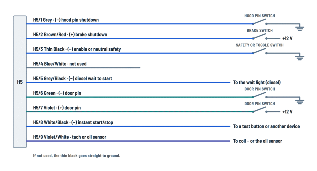
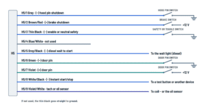
The nine wires of the black connector: safety shutdowns, doors, diesel and tach.
Terminals and components · 8
- Safety and control
- Doors
- Engine
Installation
Route the wire through a firewall grommet to the hood pin switch.
With an alarm
If an alarm also uses the hood pin switch, connect this wire through a diode.
Why
If someone presses the brake to shift without the key, the remote start shuts off.
Manual transmission
Also connect it to the handbrake, with isolation diodes between the handbrake and brake light circuits. If the handbrake wire shows 0 V at rest, a relay is needed.
Important
If you do not use this input, connect it straight to ground: without ground the remote starter will not work.
Uses
- Optional toggle switch to disable it for service or in an enclosed area.
- To the vehicle's neutral safety switch.
Reverse polarity
If the wire shows +12 V with the light out, a relay is needed to invert the signal.
Programming
Program the module for diesel mode.
Manual transmission
With a manual transmission, a door input (this or H5/7) must be connected.
Manual transmission
With a manual transmission, a door input (this or H5/6) must be connected.
Programming
Its operation depends on the alarm feature programming.
Tach
- To the coil − (conventional ignition); not needed in voltage checking mode.
- Meter on AC volts: between 1 and 6 V at idle, rising with rpm.
- Do not test it with a test light or logic probe.
Oil sensor
Type Key «On» Running Negative +12 a 14 V +2 a 3 V Positive +2 a 3 V +12 a 14 V Programming
Program the signal type (tach or oil sensor) before trying to remote start.
H7 harness: outputs
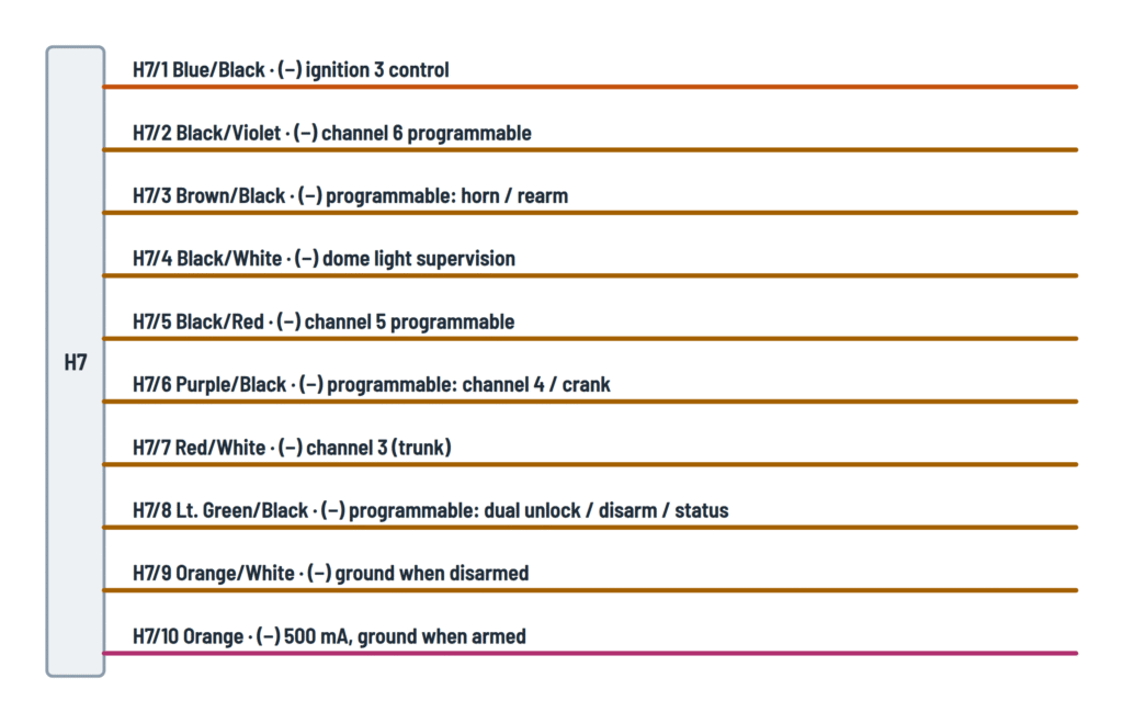
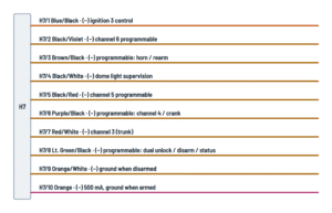
The ten negative outputs of the white connector and what each one does.
Terminals and components · 10
- Ignition 3
- (−) 200 mA outputs
- Starter disable
Ignition 3
Some vehicles have a third ignition wire needed to start and keep the engine running. Do not connect vehicle circuits together: they are isolated for a reason.
Negative output
It gives ground (200 mA max) when active: to drive relays or inputs, not loads directly.
Negative output
It gives ground (200 mA max) when active: to drive relays or inputs, not loads directly.
Negative output
It gives ground (200 mA max) when active: to drive relays or inputs, not loads directly.
Negative output
It gives ground (200 mA max) when active: to drive relays or inputs, not loads directly.
Negative output
It gives ground (200 mA max) when active: to drive relays or inputs, not loads directly.
Negative output
It gives ground (200 mA max) when active: to drive relays or inputs, not loads directly.
Negative output
It gives ground (200 mA max) when active: to drive relays or inputs, not loads directly.
Start status
Option 3 is used to bypass a shock sensor while the engine runs on remote start.
Caution
If it does not go straight to the body control module (BCM), use a relay to power the device.
Relay
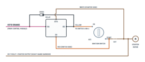
Use a relay with a diode across the coil. If you connect more than one device, diode-isolate each one.
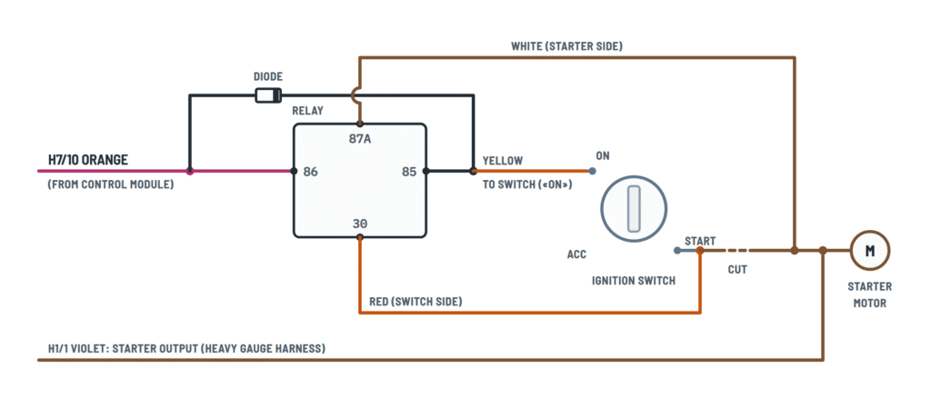
Starter disable relay (H7/10)
With the system armed, the relay prevents cranking with the key; remote start still works.
Terminals and components · 6
- Armed output
- Switch side
- Starter side
- Relay
Relay
Use a relay with a diode across the coil. If you connect more than one device, diode-isolate each one.
Operation
With the system armed, H7/10 grounds, the relay pulls in and opens 30–87A: the key cannot crank the engine.
Diode
The diode goes across the coil, with the band (cathode) on the 12 V side.
Test
With the system armed, the engine must not crank with the key.
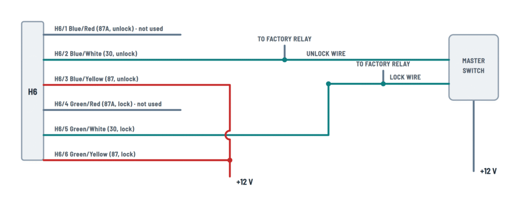
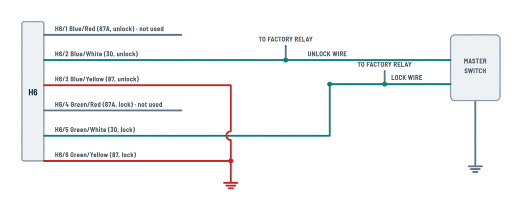
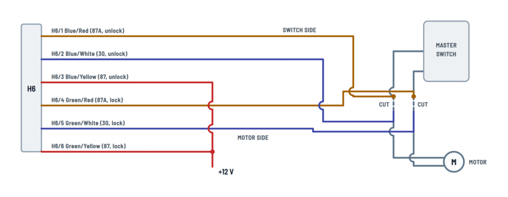
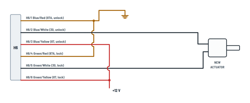
H6 harness: door locks
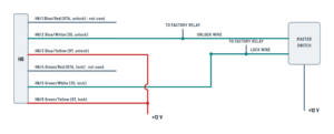
The two internal H6 relays wired for the vehicle's door lock type.
Terminals and components · 2
- Commons (30)
- Commons (30)
- Actuator
- Rest (87A)
- Active (87)
Finding the wires
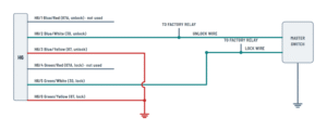
With a multimeter at the master switch: the unlock wire changes voltage only when unlocking, and the lock wire only when locking.
Vacuum locks
On vacuum systems (e.g., Mercedes-Benz and Audi), program the door lock timer for 3.5 seconds.
Direction
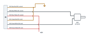
If the actuator unlocks when it should lock, swap its two wires.
At rest
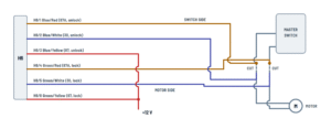
With the relays at rest, 87A joins both sides of each cut and the doors work as stock.
New actuator
At rest both actuator wires sit at ground; each relay sends +12 V on one wire to unlock or lock.
Positive system
The master switch sends +12 V on the unlock or lock wire to the factory relay. 87A is not used.
Negative system
The master switch sends ground on the unlock or lock wire to the factory relay. 87A is not used.
Reversing polarity
The motors get +12 V on one wire and ground on the other through the switch: both wires are cut and the relays go in between.
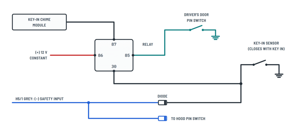
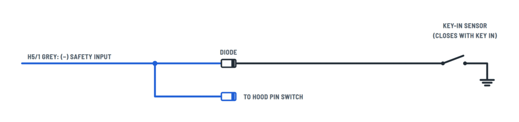
Key-in sensor
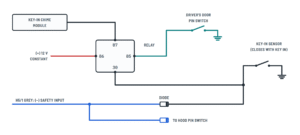
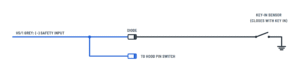
Two ways to make the remote start shut down if the key is left in.
Terminals and components · 8
- Safety input
- Sensor, diode and relay
- Door
- +12 V
Why
It keeps the vehicle from running on remote start if someone leaves the key in and shifts into gear.
How to connect it
- Cut the wire between the door pin switch and the sensor; the cylinder side goes to ground.
- Cut the wire between the chime module and the sensor; the cylinder side goes to relay 30 and the diode.
How to connect it
Cut the wire between the door pin switch and the sensor; the cylinder side goes to grey H5/1 through the diode.
Caution
With this method, the factory key-in chime and other warning tones may stop working.
About This Diagram
These diagrams are redrawn from pages 7–8, 15–16, 20 and 38–39 of the Bulldog Security Deluxe 500 manual, and we offer them completely free and in English. We have also categorized it in the Intercoms, Access & Alarms (Data, Network & Security) section on Diagramverse, and it has been rated by 1 user with an average rating of 5.0. If you have any specific questions about the Bulldog Security Deluxe 500 Wiring Diagram, we suggest checking the Frequently Asked Questions (FAQs) section.
Printable Bulldog Security Deluxe 500 Wiring Diagrams
Wiring Instructions
Before you start
For your Bulldog Security Deluxe 500, gather a digital multimeter, wire strippers, crimp or solder tools, electrical tape, zip ties and inline fuse holders. You need two 20 A fuses for the reds H1/2 and H1/3, a 3 A fuse for the red H2/5 and the 10 A fuse for the parking light circuit. Add a 12 V automotive relay for each of the starter disable, ignition 3 and channel 6 outputs you plan to use. If you install a key-in sensor, also get 4003 series diodes. On the power, starter, ignition and accessory circuits, use wire at least as heavy as the factory wire you tap. The inputs and the negative outputs carry 500 mA or less.
Disconnect the battery before wiring, and don't plug any harness into the module until every connection is finished. Find the airbag wiring (yellow tube) and never probe or tap it. To identify each wire at the ignition switch, reconnect the battery, cycle the key through Off, Acc, On and Start while you measure, then disconnect the battery again. If the vehicle has a factory immobilizer you can't identify, or you aren't comfortable with automotive wiring, hire a professional installer. Also check local rules on unattended idling.
Step-by-step wiring
- Mount the module under the dash, away from heat, pedals and steering parts.
- Connect the black H2/3 system ground to a clean, bare-metal point on the vehicle frame.
- Connect the red H2/5 system +12 V to a constant +12 V source through its 3 A fuse.
- At the ignition harness, connect the reds H1/2 and H1/3 to a high-current +12 V source, each through its own 20 A fuse. Leave the fuses out until the end.
- Connect the yellow H1/4 to ignition 1 and the pink H1/5 to the second ignition wire (cap it if unused). Connect the brown H1/6 to the heater/AC accessory wire that drops to 0 V in Start, and the violet H1/1 to the starter wire that shows 12 V only in Start.
- Set the violet transmission loop: leave it intact for an automatic, or cut it and tape both ends for a manual.
- For anti-start protection, follow the Starter disable view. Cut the starter wire, then take the switch side to relay 30 and the starter side to 87A. Wire coil 86 to the orange H7/10 and 85 to 12 V in On. Connect the violet H1/1 to the starter side, after the relay.
- Wire the H5 safety inputs: grey H5/1 to the hood pin switch and brown/red H5/2 to the light side of the brake switch. If you don't use an enable device, connect the thin black H5/3 to ground. On diesels, connect the grey/black H5/5 to the wait to start light.
- Connect the door input that matches your vehicle: green H5/6 if the door switch wire shows ground with a door open, or violet H5/7 if it shows +12 V. If you want a running-engine signal, connect the violet/white H5/9 to the coil negative or the oil pressure sensor.
- Choose the H6 lock variant by testing the master switch wires while you press lock and unlock. A +12 V pulse means Positive trigger (type A). A ground pulse means Negative trigger (type B). Wires that reverse polarity to the motors mean 5-wire (type C). No factory power locks means New actuator.
- Connect the white H2/2 to the parking light feed. For +12 V lights, the red/white H2/1 is already joined to the red wire.
- Use the H7 outputs as needed. Always go through a relay for channel 6 and ignition 3. Keep the horn output brown H2/4 within its 200 mA limit.
- If the vehicle has a key-in sensor, use Method 1 (with relay) to keep the key-in chime working, or Method 2 (diodes only). Point the diode stripe toward the sensor.
- Mount the transceiver antenna H3 inside the windshield. Put the valet switch H8 where it's hidden but within reach, and the status LED H9 in a 6 mm hole where it's easy to see.
- Insulate every splice, plug in the harnesses, install the fuses and reconnect the battery.
Testing and start-up
With the key off, measure 12 V at the red H2/5 and at both reds on H1. Then cycle the key and check three readings: the yellow H1/4 has 12 V in On and Start, the brown H1/6 has 0 V in Start, and the violet H1/1 has 12 V only in Start. Program the remotes, close the hood and do a remote start. The engine should crank, keep running and keep the heater/AC powered. Opening the hood or pressing the brake must shut the engine down at once. For testing, a ground pulse on the white/black H5/8 starts or stops the unit. Arm the system and confirm that the key can't crank the engine through the disable relay. Finally, verify that the vehicle won't start in any forward or reverse gear.
Safety notes
- The H1 power circuits carry high current. An unfused or loose red wire can melt insulation or start a fire.
- Never work near the yellow airbag tubing or its connectors.
- The hood pin protects you during service, so never leave H5/1 unconnected.
- Never leave a manual transmission vehicle in gear.
- Never remote start the vehicle inside a closed garage, where exhaust gases build up quickly.
Troubleshooting
| Symptom | Probable Cause | What to Check |
|---|---|---|
| Nothing responds to the remote and the LED stays dark | No constant power or a bad ground on H2 | Measure 12 V between the red H2/5 and the black H2/3. Check the 3 A fuse and confirm the ground goes to bare metal on the frame. |
| The unit beeps or flashes but never cranks | Enable input open or a safety input active | Make sure the thin black H5/3 goes to ground if no enable device is used. Check that grey H5/1 isn't grounded with the hood closed and that brown/red H5/2 reads 0 V with the brake released. |
| The engine cranks for a moment and stops right away | Brake wire on the wrong side of the brake switch | Brown/red H5/2 must go to the light side of the switch. It should read +12 V only while the brake pedal is pressed. |
| The car remote starts but the key won't crank it after disarming | Starter disable relay wired backwards or coil not powered | Check that 30 goes to the switch side and 87A to the starter side, and that 85 gets 12 V in On. Measure continuity 30 to 87A with the relay at rest. |
| The key cranks the engine even when the system is armed | Violet H1/1 landed on the switch side or relay coil not grounded | Move violet H1/1 to the starter side, after the relay. Confirm orange H7/10 gives ground while armed. |
| The engine runs but the heater or AC blower stays off | Brown H1/6 on the wrong wire | At the switch, find the wire that reads 12 V in Acc and On and 0 V in Start, then move brown H1/6 to it. |
| The engine starts and then stalls after a few seconds | Missing second ignition or anti-theft bypass not handled | Check whether the vehicle uses a second ignition wire for pink H1/5 or needs ignition 3 through a relay on blue/black H7/1. |
| The doors don't lock or unlock, or they act backwards | Wrong H6 variant or lock and unlock commons swapped | Re-test the master switch to confirm the type A, B, C or New actuator variant. Check that H6/2 goes to unlock and H6/5 to lock. |
| The 10 A parking light fuse blows when you lock with the remote | Polarity jumper wrong for the vehicle's light circuit | Check whether the lights are +12 V or ground switched. The red/white H2/1 must only be joined to the red for +12 V lights. |
| The remote start keeps running with a door opened or the key inserted | Door or key-in input on the wrong polarity, or a reversed diode | Use green H5/6 for ground-switched doors and violet H5/7 for +12 V doors. On key-in diodes, the stripe must face the sensor. |