
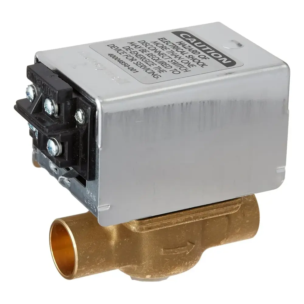
Honeywell Zone Valve V8043 24V Wiring Diagram
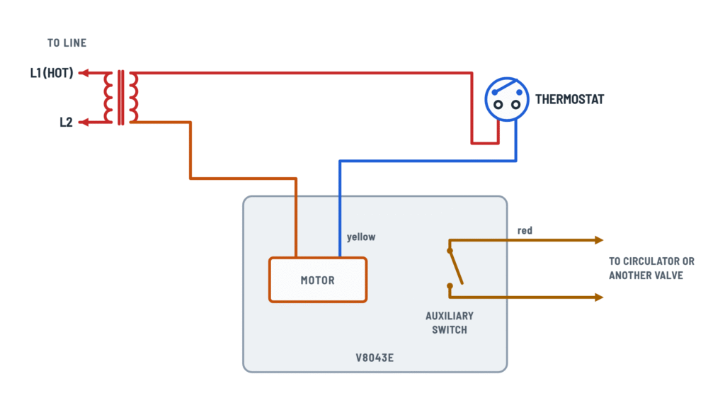
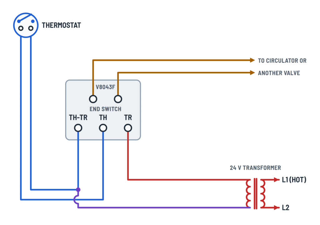
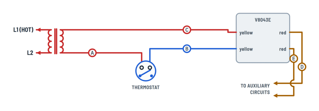
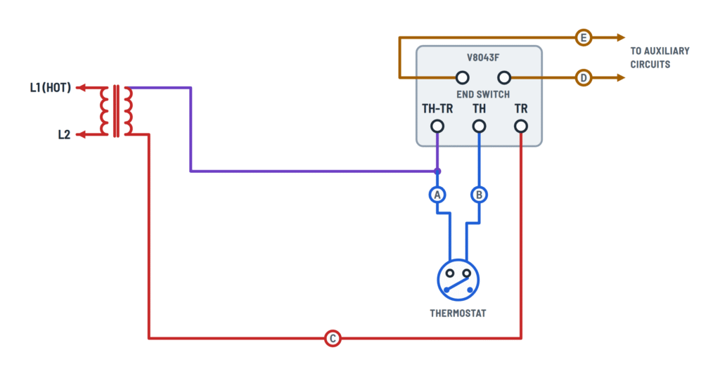
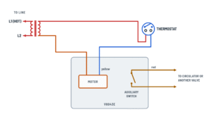
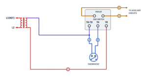
Single valve
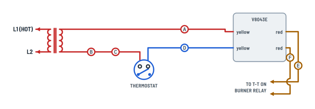
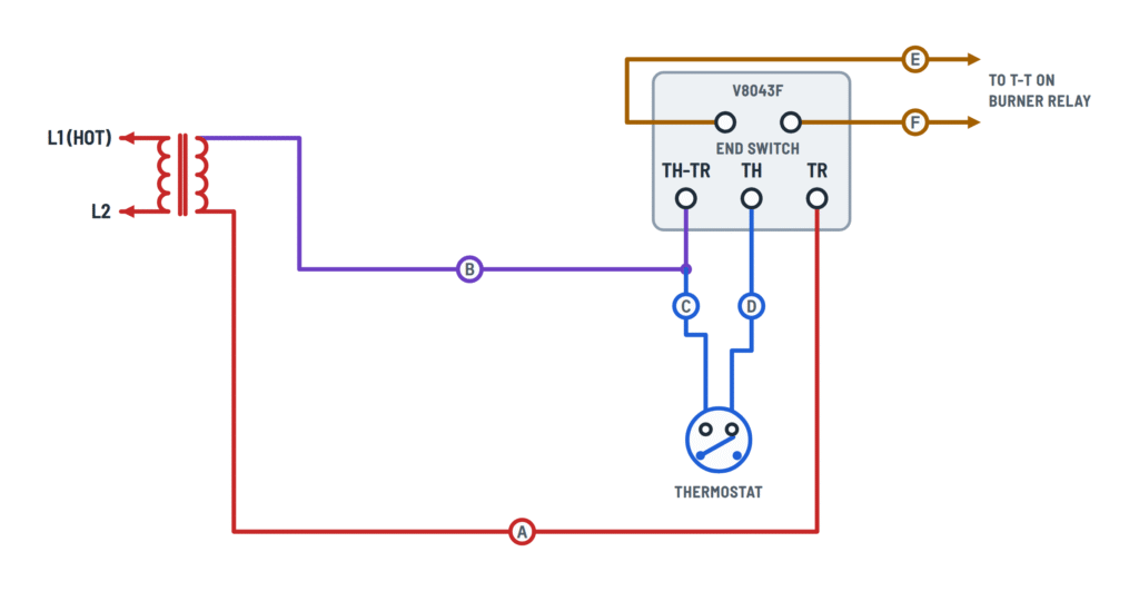
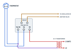
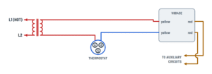
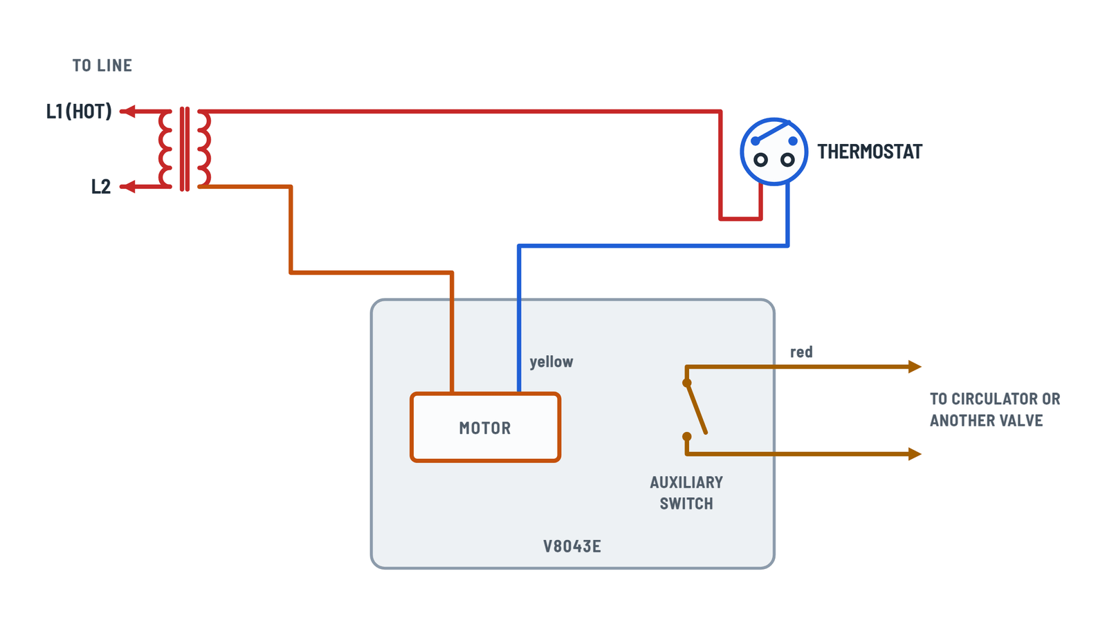
Typical wiring for one valve with its thermostat, transformer and end switch.
Terminals and components · 4
- Transformer
- Thermostat
- Motor
- TH-TR
- End switch
What it does
One secondary side goes to the thermostat, the other straight to the motor (TR or yellow lead).
Rating
- Motor: 24 V AC, 60 Hz, 0.30 A, 7.2 VA max.
Caution
The primary is on line voltage: provide a disconnect and overload protection.
What it does
On a call for heat the valve opens; at the end of its stroke the end switch closes.
Checkout
Raise the setpoint: the valve should open and start the circulator. Lower it: the valve closes and the circulator stops.
Operation
Normally closed valve: opens when powered and spring-returns closed.
Never jumper
Never jumper the motor terminals, even briefly: it can burn out the thermostat's heat anticipator.
Manual lever
In MAN. OPEN the valve opens without power (the end switch doesn't close). It returns to AUTO when energized.
Use
If you prefer, the transformer can go straight to the thermostat and TH-TR stays empty.
Rating
- 120 V: 4.4 A running, 26.4 A inrush
- 24 V: 50 VA pilot duty
Several zones
With end switches in parallel, any zone calling for heat runs the circulator.
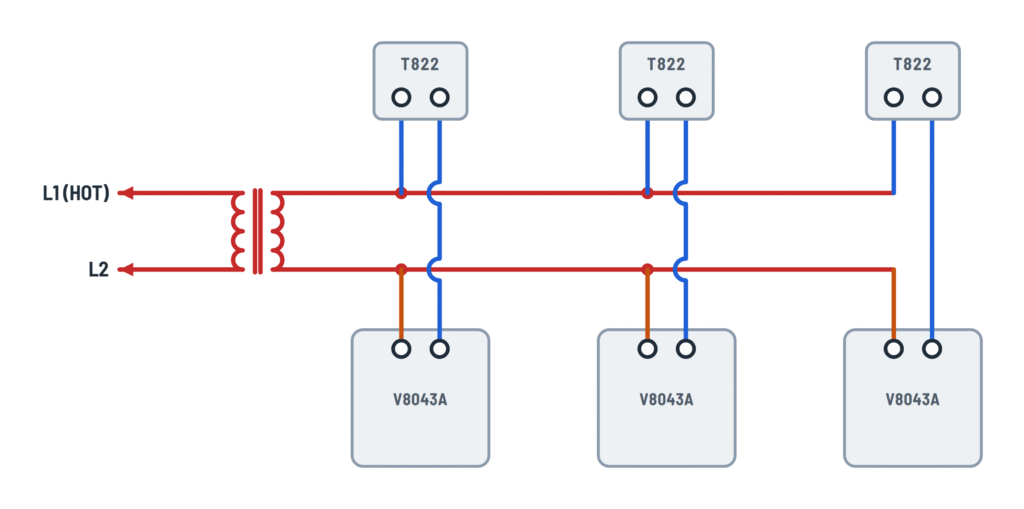
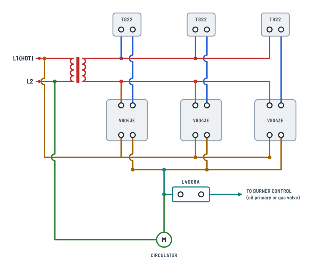
Zones with T822 thermostats
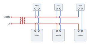
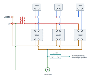
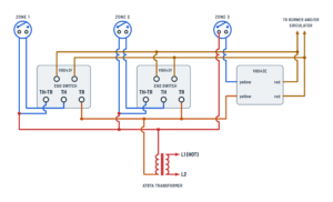
Three zones with T822 thermostats and their boiler controls.
Terminals and components · 3
- Transformer
- Thermostats
- Motor
- End switch
- Control
- Circulator
How to connect it
Thermostats and motors are connected in parallel across the secondary.
How to connect it
One terminal to the transformer, the other to its valve's motor.
V8043A
It only has motor leads (no end switch). The black lead goes to the thermostat.
V8043E
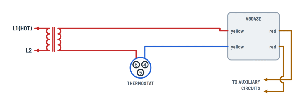
One yellow lead goes to the thermostat and the other to the transformer.
How to connect it
One red lead from each valve goes to L1 (120 V hot); the other to the L4006A and the circulator.
Caution
Here the red leads carry 120 V.
How to connect it
All valves' red leads, in parallel, to the aquastat's T and T terminals (heat call).
L4006A
High-limit aquastat: passes the call to the burner control (oil primary or gas valve transformer) while water stays below the limit.
Use
Gas or oil, no domestic hot water.
Which model
- No domestic hot water: L8148J (gas) or L8148A (oil)
- With domestic hot water: L8124E (gas) or L8124A/C (oil)
Terminals
- 1 and 2: 120 V line
- T-T: zone call
- C1-C2: circulator · B1-B2: burner
What it does
Stops when all valves are closed.
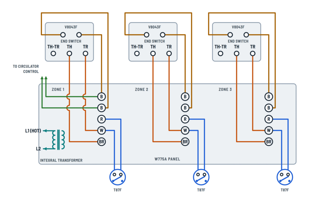
Zones with T87F thermostats
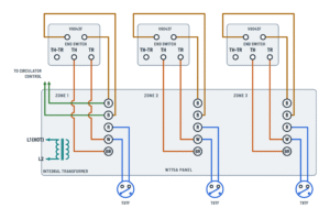
Three-zone systems with an L8124G, W775A panel or AT87A transformer (wiring repeats for each zone).
Terminals and components · 4
- Transformer
- Thermostats
- Motor
- End switch
- Control
What it does
One side feeds the thermostats (or TH-TR); the other, each motor's return (TR or yellow lead).
More zones
To add valves, use another AT87A transformer (up to five more valves).
How to connect it
One terminal of each thermostat goes to Z on the L8124G, the other to its valve's TR.
How to connect it
Each thermostat goes to its zone's R and W terminals on the panel.
How to connect it
On a V8043F, between TH-TR and TH. On a V8043E, between the transformer and one yellow lead.
V8043E or V8043F
If code permits, both can be mixed in the same system when wired this way.
Jumper on each valve
Add a jumper between one end switch terminal and TH. The TH terminals go to TV on the L8124G.
How to connect it
TH and TR go to BR and W of its zone on the panel (they cross). On a V8043E: yellow leads to W and BR.
How to connect it
All TR terminals (and one yellow lead of each V8043E) to the same side of the transformer.
Use
It doesn't connect to the motor: it's only a tie point.
How to connect it
One terminal to T on the L8124G; the other, with the jumper, to TH. When the valve opens it joins TV and T: burner and circulator start.
How to connect it
To its zone's two B terminals. On a V8043E, the red leads go to the B terminals.
How to connect it
All end switches (and the V8043E red leads) in parallel to the burner or circulator circuit.
Terminals
- TV and Z: 24 V for the zones
- T: zone call
- C1-C2: circulator · B1-B2: burner
More zones
For more than three valves, add an AT87A transformer (up to five more valves).
Terminals per zone
- R and W: thermostat
- W and BR: motor
- B and B: end switch
More zones
Each W775A handles four zones; add another for four more valves.
What it does
Starts the circulator when any zone is open.
Replacing other valves
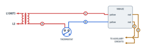
How to wire a V8043E or V8043F in place of a 3-wire Taco, Dole, Flair or White-Rodgers valve.
Terminals and components · 3
- Transformer
- Thermostat
- Motor
- TH-TR
- End switch
Existing Taco system
Taco terminal Wires 1 B (from thermostat) 2 C (transformer) and D 3 E Dole and Flair
The new wiring is the same for both brands: A and D to the motor, B spliced to C, E and F to the burner relay.
3-wire thermostat
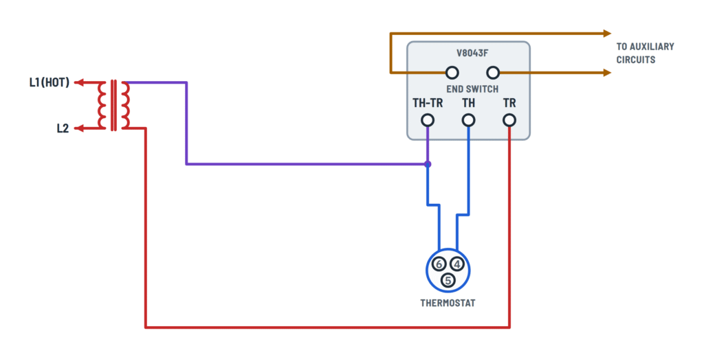
Use terminals 6 and 4. Tape the wire from terminal 5 and tuck it away.
If the transformer powers the auxiliary circuit
One red lead goes to the transformer (the same side that goes to thermostat terminal 6), the other to the auxiliary circuit.
How to connect it
Label each wire with the figure's letter before disconnecting the old valve.
Pressure
Check that the new valve's pressure rating suits the application.
Never jumper
Never jumper the motor terminals: it can burn out the thermostat's heat anticipator.
Other option
You can also wire the transformer straight to the thermostat and leave TH-TR empty.
How to connect it
The two wires from the old valve's auxiliary contact go to the end switch (red leads or top terminals).
About This Diagram
These diagrams are redrawn from pages 4–8 of the Honeywell Zone Valve V8043 24V manual, and we offer them completely free and in English. We have also categorized it in the Boilers & Zone Valves (HVAC & Water Heating) section on Diagramverse, and it has been rated by 1 user with an average rating of 5.0. If you have any specific questions about the Honeywell Zone Valve V8043 24V Wiring Diagram, we suggest checking the Frequently Asked Questions (FAQs) section.
Printable Honeywell Zone Valve V8043 24V Wiring Diagrams








Wiring Instructions
Before you start
First, pick the Honeywell Zone Valve V8043 24V tab that matches your installation. Use Complete for a single valve with its own transformer and thermostat. In that tab, choose V8043E (leadwires) if your valve has flying leads or V8043F (terminal board) if it has screw terminals. For multizone systems, use T822 zones or T87F zones and pick the variant that matches your boiler control, zone panel or extra transformer. Use Replacements when a 2-wire V8043E or V8043F is taking the place of a 3-wire Taco, Dole, Flair or White-Rodgers valve.
- Tools: screwdrivers, a wire stripper, wire nuts, electrical tape, labels and a multimeter that reads AC volts and continuity.
- Wire: No gauge is specified for this valve. 18 AWG thermostat cable is the usual choice for the 24 V wiring. Any wiring that carries 120 V, such as end switch circuits feeding a circulator, must be line-voltage wire sized for that circuit. All wiring must meet local codes.
- Transformer capacity: Each valve draws 0.30 A, 7.2 VA maximum, at 24 V AC 60 Hz. Add 7.2 VA for every valve on the same transformer, plus any other 24 V loads it already powers.
- End switch load: The end switch is rated 120 V, 4.4 A running and 26.4 A inrush, or 50 VA pilot duty at 24 V. Compare these figures with the nameplate of the circulator or relay it will switch.
Turn off the breaker or disconnect that feeds the transformer, the boiler and the circulator. Then confirm with your meter that the circuit is dead. Every line-voltage supply needs a disconnect and overload protection. This work is meant for a trained, experienced service technician. If you need a new 120 V circuit or changes inside the boiler's control wiring, hire a licensed electrician or heating contractor, and check whether your area requires a permit.
Step-by-step wiring
- Confirm the valve is mounted with the flow in the direction of the arrow on the body. On horizontal pipe, the actuator must sit level with or above the pipe centerline. When replacing a valve, label every old wire with the letters shown in the Replacements tab before you disconnect it, and note its position and color.
- Connect the 24 V transformer primary to L1 (hot) and L2 through its disconnect.
- Wire the 24 V control loop. On a V8043E, run one transformer secondary lead to the thermostat. Run the thermostat's other wire to one yellow lead, and connect the second yellow lead to the other secondary lead. On a V8043F, land one secondary lead on TH-TR and connect the thermostat between TH-TR and TH. Then run the other secondary lead to TR. TH-TR is only a tie point and does not connect to the motor.
- For multiple zones, one transformer side feeds all the thermostats and the other side goes to one motor lead, or TR, on each valve. On a V8043A, the black lead goes to the thermostat. If the total load exceeds your transformer, an AT87A transformer powers up to five more valves, and each additional W775A panel powers up to four more.
- With an L8124G aquastat, follow that variant exactly, including the jumper added on each valve. With a W775A panel, wire each zone to its own row: thermostat on R and W, TH to BR, TR to W, and the end switch to the zone's two B terminals.
- Wire the end switch: the two red leads on a V8043E, or the two top terminals on a V8043F. On a single valve, it starts the circulator or another valve. In multizone systems, wire all end switches in parallel so that any open zone runs the circulator and burner. In the L4006A variant, the red leads connect to L1 (120 V) and the L4006A. In the aquastat and Dole/Flair variants, they go to the T-T terminals.
- For a White-Rodgers replacement, use thermostat terminals 6 and 4. Tape the unused wire from terminal 5 and tuck it away. If the old transformer also powered the auxiliary circuit, use the alternate wiring shown for that case.
- Tighten every connection and tug-test each wire nut. Keep the 24 V wiring physically separated from the 120 V wiring, then refit the actuator cover.
Testing and start-up
Restore power and measure the transformer secondary; it should read about 24 V AC. Raise the zone thermostat above room temperature. The valve should open smoothly. At the end of the opening stroke, the end switch should close and the circulator or burner circuit should start. While the thermostat is calling, you should read about 24 V AC across the two yellow leads, or across TH and TR.
Lower the setpoint below room temperature. The spring should close the valve, the voltage across the motor should drop to zero and the auxiliary equipment should stop. Repeat this on every zone, and check that each valve goes from closed to open and back to closed without sticking. If you opened the valve by hand, the manual lever releases automatically the first time the motor is powered.
Safety notes
- The transformer primary and, in many layouts, the end switch carry 120 V even though the thermostat side is 24 V. Treat the red leads as live unless you have confirmed otherwise.
- Never jumper the motor terminals, not even briefly. Doing so can burn out the heat anticipator in the thermostat.
- Do not exceed the end switch rating. As a general rule, use a properly rated relay for any load larger than the rating.
- Keep the valve where the ambient temperature stays at or below 125°F and the fluid stays at or below 200°F.
Troubleshooting
| Symptom | Probable Cause | What to Check |
|---|---|---|
| Nothing happens when the thermostat calls: the valve doesn't move and there's no hum | No 24 V: tripped breaker, open disconnect, or the transformer primary isn't wired to L1 and L2 | Measure the transformer secondary; you should read about 24 V AC. If it reads zero, check for 120 V on the primary and inspect the breaker and disconnect. |
| The transformer has power, but a V8043F valve won't open on a call for heat | The thermostat is landed on TR instead of TH, or the transformer lead is on TH instead of the TH-TR tie terminal | With the thermostat calling, measure across TH and TR; it should read about 24 V AC. Rewire so that the transformer goes to TH-TR, the thermostat runs between TH-TR and TH, and the other transformer side goes to TR. |
| The valve opens but the circulator or burner never starts | The end switch isn't wired, is wired to the wrong terminals, or the auxiliary circuit has no power | With the valve fully open and the power off, check continuity across the red leads or the two top end switch terminals; they should read closed. Then confirm the circuit they feed has its supply, for example L1 or the T-T terminals. |
| I opened the valve with the lever and the pump doesn't run | Normal: the end switch does not close when the valve is opened manually | Use the thermostat to open the valve. The lever releases on the next electrical operation, and the end switch then closes at the end of the opening stroke. |
| Only one zone starts the circulator, or the pump runs only when all zones call | End switches wired in series, or only one zone's end switch is connected | Rewire all end switches in parallel to the circulator or burner circuit. Test each zone on its own: every zone should start the circulator. |
| The valve stays open after the thermostat is satisfied | A short or jumper across the thermostat wires or motor leads, or the lever is locked at MAN. OPEN | With the thermostat satisfied, measure across the motor leads; it should read 0 V. Look for a nicked cable or leftover jumper, and check the lever position. |
| The thermostat stopped controlling after someone jumpered the valve wires | The thermostat's heat anticipator burned out | Repair or replace the thermostat, and never jumper the valve coil terminals again. |
| Valves open slowly or not at all when several zones call, and the transformer runs hot | The transformer is undersized for the number of valves | Add 7.2 VA per valve and compare the total with the transformer's VA rating. Measure the secondary with all zones calling. Add an AT87A transformer or another W775A panel if needed. |
| The new valve runs nonstop or ignores the thermostat after replacing a 3-wire valve | Old wires were mismatched, or terminal 5 on a White-Rodgers thermostat was left connected | Match every wire to its letter in the Replacements variant for your old brand. On White-Rodgers systems, use terminals 6 and 4 only, and tape the wire from 5. |
| The end switch contacts are pitted or the circulator stutters | The circulator draws more than the end switch rating | Check the circulator nameplate against 4.4 A running and 26.4 A inrush at 120 V. If it's higher, switch the circulator through a properly rated relay. |
| Zones open but the boiler never fires, in a system with an aquastat | The red leads aren't on the aquastat's T-T terminals | Confirm the end switches are in parallel on T-T. With a zone open, check continuity across T-T at the aquastat; it should read closed. |