
Truck-Lite Signal Stat 900 Warning Switch Wiring Diagram

Turn signals, hazard and stop lights
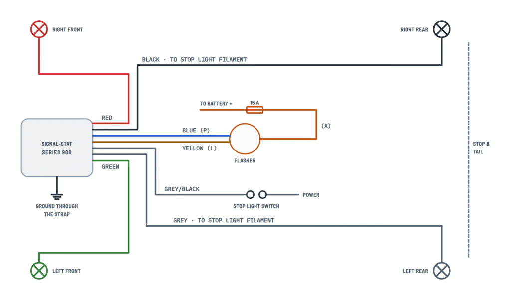
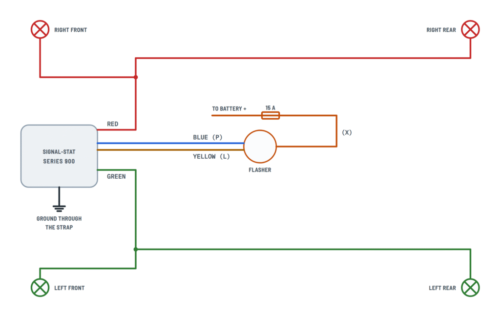
Switch wires to the lamps, the flasher and the stop light switch.
Terminals and components · 9
- Right turn
- Left turn
- Stop
- Pilot (P)
- Load (L)
- Power (X)
- Stop and grey
Splices
Cut and splice the wires as required; tape the ends of unused wires.
Splices
Cut and splice the wires as required; tape the ends of unused wires.
Separate circuits
The right and left rear stop lamps must be on separate circuits; the line joining them in the figure is the tail lamp circuit only.
Pilot stays on
If the pilot light stays on, the blue and yellow are connected together. With a 2-terminal flasher, the blue is not used.
Always hot
The power lead must be hot with the ignition off for the hazard warning to work.
LED
With LED lamps, a solid-state LED flasher is needed.
If nothing works
Check the ground or run a separate wire from the anchor clip to the chassis. A pilot light that does not work usually means a poor ground.
High and low beams (model 905)
The model 905 handle button switches the beams through the 129 relay.
Terminals and components · 5
- Button (white)
- Low
- High
- Power
- Ground
About This Diagram
These diagrams are redrawn from pages 2–3 of the Truck-Lite Signal Stat 900 Warning Switch manual, and we offer them completely free and in English. We have also categorized it in the Vehicle Lighting (Automotive) section on Diagramverse, and it has been rated by 1 user with an average rating of 5.0. If you have any specific questions about the Truck-Lite Signal Stat 900 Warning Switch Wiring Diagram, we suggest checking the Frequently Asked Questions (FAQs) section.
Printable Truck-Lite Signal Stat 900 Wiring Diagrams



Wiring Instructions
Before you start
First, pick the right tab for your Truck-Lite Signal Stat 900. Models 900, 901, 910 and 905 use the variant with separate rear wires. On those, Black and Grey feed the rear stop light filaments, so the rear lamps work as both stop and turn lights, and Grey/black goes to the stop light switch. Models 902 and 903 use the simpler variant, where Red and Green feed both the front and rear turn lamps on their side. Only model 905 has the Hi/Lo beams tab with relay 129.
You will need a 3-terminal flasher and socket (not included with the switch), a 15 A fuse and holder, crimp splices or solder and heat shrink, electrical tape, a wire stripper, a test light or multimeter, and sandpaper or a scraper for the steering column. The switch has no specified wire gauge. Match the gauge of the vehicle's existing lighting circuits and never splice in a thinner wire. If your lamps are LED, get a solid-state flasher designed for LED loads.
Turn the ignition off before you start. Pull the flasher out of its socket and leave it out until all wiring is finished and checked. On a model 905, disconnect the battery ground cable before you touch the headlamp circuit. This is a 6, 12 or 24 V vehicle circuit, so you normally don't need a permit. Have an automotive electrician do the job if the vehicle is under warranty, subject to commercial inspection, or you are unsure how its lighting is wired.
Step-by-step wiring
- Mount the switch on the steering column with the strap, anchors and clips. Scrape the paint off the column under the strap so the ground is bare metal to metal. The switch has no ground wire of its own, so the flashing and the pilot lights depend on this contact. Tighten the screws evenly.
- Install the 3-terminal flasher socket. Run the X terminal to the battery through the 15 A fuse. Use a line that is hot with the ignition off, or the hazard warning will not work with the engine stopped.
- Connect Yellow (L) to the flasher L terminal. This is the switch's flashing power. Connect Blue (P) to the flasher P terminal to drive the green and red pilot lights. Wagner and Tridon flashers label their terminals B for battery, L for load and E for pilot, so on those Blue goes to E.
- Cut and splice Red to the right front turn lamp and Green to the left front turn lamp. On models 902 and 903, these same wires also feed the right and left rear turn lamps.
- On models 900, 901, 910 and 905, splice Black to the right rear stop light filament and Grey to the left rear stop light filament. The left and right rear lamps must be on separate circuits, never tied together. Leave the tail light circuit as it was.
- Connect Grey/black to one pole of the stop light switch and bring battery power to the other pole. If the poles are marked, Grey/black goes to the negative side.
- Tape the end of each unused wire separately so it cannot short.
- Model 905 only, with the battery ground cable still off: connect the White button lead to relay 129 terminal 85 and Purple headlamp power to terminal 30. Run White/green from terminal 87A to the low beams and Yellow/black from terminal 87 to the high beams. Bolt the relay's White lead to clean chassis metal for ground.
- Check every splice for bare copper and stray strands, compare each wire color against the diagram, then refit the flasher. On a 905, reconnect the battery ground cable last.
Testing and start-up
Turn the ignition on and move the handle in the direction of a turn. The front and rear lamps on that side should flash, and the green pilot light should flash with them. Put the handle back in neutral and the signal should stop. Press the brake pedal: both rear stop lights should light steadily. During a turn, the rear lamp on the turning side should flash while the other one stays lit.
Next, turn the ignition off and pull the flare tab out. All the turn lamps and the red pilot light should flash. On a model 905, press the handle button: the headlamps should switch between low and high beams with each press.
To measure, use a test light or multimeter. The flasher X terminal should show full battery voltage with the ignition off, and the L terminal should pulse when you select a turn. Resistance between the switch housing and the battery negative post should be close to zero ohms.
Safety notes
- Always protect the flasher feed with the 15 A fuse, mounted as close to the battery connection as you can. An unfused battery line can overheat and start a fire if it shorts.
- The flasher feed stays hot with the key off. Treat it as live at all times and disconnect the battery before you rework it.
- Keep wires away from the steering shaft, pedals, exhaust and sharp edges, and secure them so the moving column cannot pull on them.
- Use only the correct pilot bulb: #51 for 6 volt, #53 for 12 volt and #356 for 24 volt service. Test a new bulb only after the switch is reassembled and grounded.
Troubleshooting
| Symptom | Probable Cause | What to Check |
|---|---|---|
| Nothing works at all: no turn signals, no hazards, no pilot lights | Poor ground at the mounting strap, blown 15 A fuse or no power at the flasher | Remove the strap, scrape the column down to bare metal and refit it, or run a separate ground wire from under the anchor clip to the chassis. Check the fuse and confirm battery voltage at flasher terminal X. |
| Hazards flash but the turn signals don't | Weak ground between the strap and the steering column, wrong wire colors or a short at a splice | Remake the metal-to-metal contact under the strap. Recheck every wire color against the diagram and look for bare or touching conductors at each splice. |
| Pilot light on the switch stays on solid | Blue (P) and Yellow (L) connected together | Separate the two wires. Blue goes only to the flasher P terminal (E on Wagner/Tridon) and Yellow goes only to L. |
| Lamps flash but the green and red pilot lights never come on | 2-terminal flasher with no P terminal, Blue not connected, burned-out pilot bulb or poor ground | Fit a 3-terminal flasher with Blue on P. Check the bulb type (#51, #53 or #356 to match the system voltage) and the strap ground. |
| Hazards don't work with the engine off | Flasher X fed from a circuit that is switched by the ignition | With the key off, measure X to ground. If you don't read battery voltage, move the feed to an always-hot line through the 15 A fuse. |
| Both rear brake lamps come on or flash together when signaling | Left and right rear lamps tied together on one circuit | Separate the rear lamps: Black to the right rear stop filament only, Grey to the left rear stop filament only. Leave the tail light circuit separate. |
| Brake lights don't work after the installation | Grey/black not on the stop light switch, or no power on the switch's other pole | With the pedal released, confirm battery voltage on one pole. Press the pedal and confirm the voltage reaches the Grey/black pole. |
| LED lamps flash very fast, stay on or don't flash | Standard flasher used with LED lamps | Install a solid-state flasher designed for LED lighting. |
| Brand-new 6 V flasher does nothing | Flasher damaged out of the box. 6 V flashers often break in shipping | Try another flasher before you rewire anything. Some installers need two or three before finding a good one. |
| Vehicle has separate turn and hazard flashers and only one function works | Original two-flasher system not adapted to the switch | Jumper the two flasher power terminals, connect Yellow to one L terminal and run Blue to the P terminal of both flashers. Or reroute the system to use a single flasher. |
| Pilot lights don't work with a Wagner or Tridon flasher | Blue connected to the wrong terminal, because these brands label terminals differently | On these flashers, B is battery, L is load (Yellow) and E is pilot (Blue). Move Blue to E. |
| Model 905 button does nothing or one beam never lights | Relay 129 not grounded, or leads on the wrong relay terminals | Check that the relay White lead is bolted to clean chassis metal and that Purple on 30 has voltage. Confirm White is on 85, White/green on 87A and Yellow/black on 87. |