
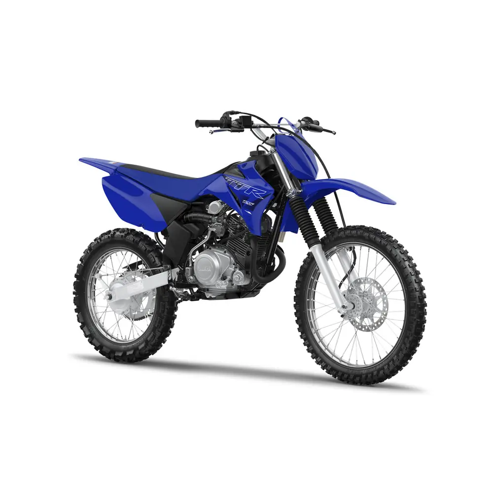
Yamaha TT-R125LWE Motorcycle Wiring Diagram
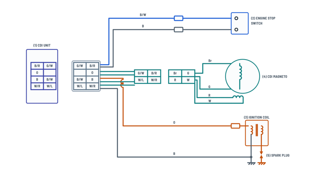
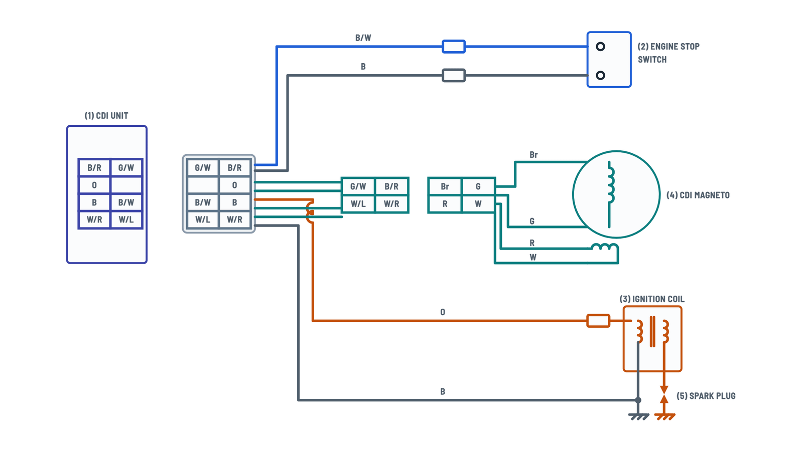
Ignition circuit
CDI unit, engine stop switch, magneto, coil and spark plug; tap any wire to see what it does.
Terminals and components · 5
- CDI
- Stop (B/W)
- Ground (B)
- Magneto
- Ignition (O)
Components
No. Component 1 CDI unit 2 Engine stop switch 3 Ignition coil 4 CDI magneto 5 Spark plug Colors
Code Color B Black Br Brown G Green O Orange R Red W White B/R Black/red B/W Black/white G/L Green/blue G/W Green/white W/L White/blue W/R White/red Check
This diagram shows only the ignition circuit: it does not include the LWE's electric starter, battery or main switch.
Check
The colors change across the connector; the drawing does not show for certain which harness wire mates with which magneto wire.
About This Diagram
This diagram is redrawn from the Yamaha TT-R125LWE Motorcycle manual, and we offer it completely free and in English. We have also categorized it in the Motorcycles (Powersports) section on Diagramverse, and it has been rated by 1 user with an average rating of 5.0. If you have any specific questions about the Yamaha TT-R125LWE Motorcycle Wiring Diagram, we suggest checking the Frequently Asked Questions (FAQs) section.
Printable Yamaha TT-R125LWE Wiring Diagrams
Wiring Instructions
Before you start
The Yamaha TT-R125LWE diagram shows only the ignition circuit: the CDI unit, the Engine stop switch, the CDI magneto and its connector, the Ignition coil and spark plug, and the Black ground wire that ties them together. Your TT-R125LWE also has a 12 V battery, a 10.0 A main fuse, a main switch, an electric starter and a starting circuit cut-off system with clutch and neutral switches. Those parts are not drawn here, so check them separately if your problem involves cranking rather than spark.
Gather these tools and parts:
- A pocket tester or multimeter with low-ohm and kΩ ranges. Yamaha's own tool is the YU-03112/90890-03112.
- A dynamic spark tester (YM-34487) or ignition checker (90890-06754). If you don't have one, use an inline spark tester.
- A wire thickness gauge for the plug gap and a torque wrench.
- Electrical contact cleaner, dielectric grease, and heat-shrink or new connector terminals.
The sources don't specify wire gauge. If you have to splice or replace a wire, use automotive-grade stranded wire at least as heavy as the original, and keep the same color code so the next person can follow the harness.
Isolate power before you touch anything. Stop the engine, turn the main switch to OFF and remove the key. If you'll be working near the starter or battery wiring, also disconnect the battery behind panel B: negative lead first, then positive. Let the engine and exhaust cool. To reach the ignition wiring, remove the seat and the fuel tank. Set the fuel cock to OFF first, and work in a ventilated area away from sparks and flames.
This is a 12 V vehicle and no permit is needed. If you aren't comfortable with resistance testing or the faults persist, take the bike to a Yamaha dealer.
Step-by-step wiring
- Inspect every coupler first. Unplug each connector in the ignition circuit and look for rust, dust, loose pins and signs of short circuits. Clean or replace any terminal that fails, then reconnect it until it latches.
- Establish the ground. Route the B (black) wire to its frame ground point. Clean the contact surface down to bare metal and tighten the fastener. The CDI unit, the engine stop switch and the ignition coil all depend on this one common ground.
- Connect the CDI magneto. Join the four harness wires (G/W, B/R, W/L, W/R) to the magneto connector. On the magneto side, the Brown and Green leads belong to the charging coil and the Red and White leads belong to the pickup coil. Reconnect the coupler halves exactly as they mate from the factory. Don't cut and re-pin wires by guesswork.
- Wire the engine stop switch. Connect its B/W lead to the harness B/W wire that runs to the CDI unit, and its B lead to the black ground. Route the leads along the handlebar so that turning the bars from lock to lock doesn't stretch or pinch them.
- Connect the ignition coil. Run the O (orange) wire from the CDI unit to the coil primary terminal. Make sure the coil's ground or mounting is clean and tight.
- Plug in the CDI unit. Seat the seven-wire connector fully: B/R, G/W, O, B, B/W, W/R and W/L. Before you plug it in, check that no pin has backed out of the housing.
- Fit the spark plug. Use an NGK CR7HSA gapped to 0.6–0.7 mm (0.024–0.028 in). Torque it to 13 N·m (9.6 lb·ft), then push the plug cap on firmly.
- Secure the harness. Clamp the wires away from the exhaust, the cylinder head fins and the drive chain. Then refit the fuel tank and the seat.
Testing and start-up
Do these resistance checks with the coupler disconnected and the parts at about 20 °C (68 °F):
- Engine stop switch: put the tester's positive lead on B/W and the negative lead on B. You should read continuity while the button is pushed and no continuity when it's released.
- Ignition coil primary: measure from the orange lead (positive) to the black lead (negative). You should read 0.18–0.28 Ω.
- Ignition coil secondary: remove the plug cap and measure from the spark plug lead (positive) to the orange lead (negative). You should read 6.3–9.5 kΩ.
- Pickup coil: measure from the red lead (positive) to the white lead (negative). You should read 248–372 Ω.
- Charging coil: measure from the brown lead (positive) to the green lead (negative). You should read 688–1,032 Ω.
Next, do a spark test. Connect the spark tester between the plug cap and the spark plug, then kick the kickstarter. You need a spark that jumps a gap of at least 6.0 mm (0.24 in). Finally, start the engine, let it warm up, and press the engine stop button. The engine should die at once.
The CDI unit has no simple bench test. Replace it only after every other component and connection checks good, then repeat the checks above.
Safety notes
- The coil secondary and spark plug lead carry high voltage whenever the engine turns, even when you only kick it over. Never hold the plug lead or cap while cranking.
- When cranking with the plug out, ground the plug electrodes against the cylinder head. This keeps stray sparks away from fuel vapor.
- Never test spark with the fuel tank open or fuel spilled nearby. Gasoline vapor ignites easily.
- Don't run the engine indoors or in a closed garage, because the exhaust contains carbon monoxide.
- If you replace the fuse, use the specified 10.0 A. A higher rating can let a short damage the wiring or start a fire.
Troubleshooting
| Symptom | Probable Cause | What to Check |
|---|---|---|
| Engine won't start and there's no spark at the plug | Loose, corroded or unplugged coupler somewhere in the ignition circuit | Unplug and inspect every connector, including the seven-wire CDI connector and the magneto connector. Clean any rust or dust, re-seat pins that have backed out, and reconnect until each one latches. |
| No spark, but all the connectors look fine | Engine stop switch stuck closed, or its B/W wire shorted to ground | Disconnect the switch and check from B/W to B. You should read no continuity when released and continuity when pushed. If the switch tests good, look along the B/W wire for chafed insulation touching the frame. |
| Pressing the stop button doesn't kill the engine | B/W or B wire to the stop switch broken or disconnected, or switch contacts worn | Check for continuity from B/W to B with the button pushed. If you read continuity there, the switch is good: trace the B/W wire back to the CDI connector and the B wire to the frame ground. |
| Weak spark or misfiring, especially when hot | Poor ground on the black wire or coil mounting | Clean the frame ground point and coil mounting to bare metal and tighten them. Check that the spark jumps at least 6.0 mm (0.24 in) on a spark tester. |
| Spark is present but very weak or intermittent | Ignition coil primary or secondary winding out of spec | Measure the primary from orange to black: 0.18–0.28 Ω. Measure the secondary from the plug lead to orange with the cap removed: 6.3–9.5 kΩ. Replace the coil if either reading is out of range. |
| No spark after the magneto connector was disturbed | Magneto wires mismatched or a pin pushed back in the coupler | Reconnect the factory coupler halves without re-pinning. Then check the pickup coil from red to white (248–372 Ω) and the charging coil from brown to green (688–1,032 Ω). |
| Engine dies or cuts out over bumps | Chafed harness or a loose spade connector at the coil or stop switch | With the engine off, wiggle each section of the harness while watching the ohmmeter. Re-route any wires that touch the frame edges, chain or exhaust. |
| Spark plug fouled wet and there's no spark after a lot of cranking | Fouled plug, or plug gap out of range after work | Dry and clean the plug or fit a new NGK CR7HSA, gapped to 0.6–0.7 mm. Retest the spark, then try starting with the throttle half open. |
| Engine cranks slowly or not at all with the start switch | Discharged battery, loose battery leads or a blown 10.0 A fuse. This is outside the ignition diagram. | Tighten the battery leads and charge the battery with a constant-voltage charger. Replace the fuse with a 10.0 A unit only. If it blows again immediately, have the wiring checked. |
| Every component tests in spec but there's still no spark | Faulty CDI unit | Recheck all the connections and components first. If none of them is at fault, replace the CDI unit and then repeat the component checks. |