Honeywell Aquastat Relay L8148J Wiring Diagram
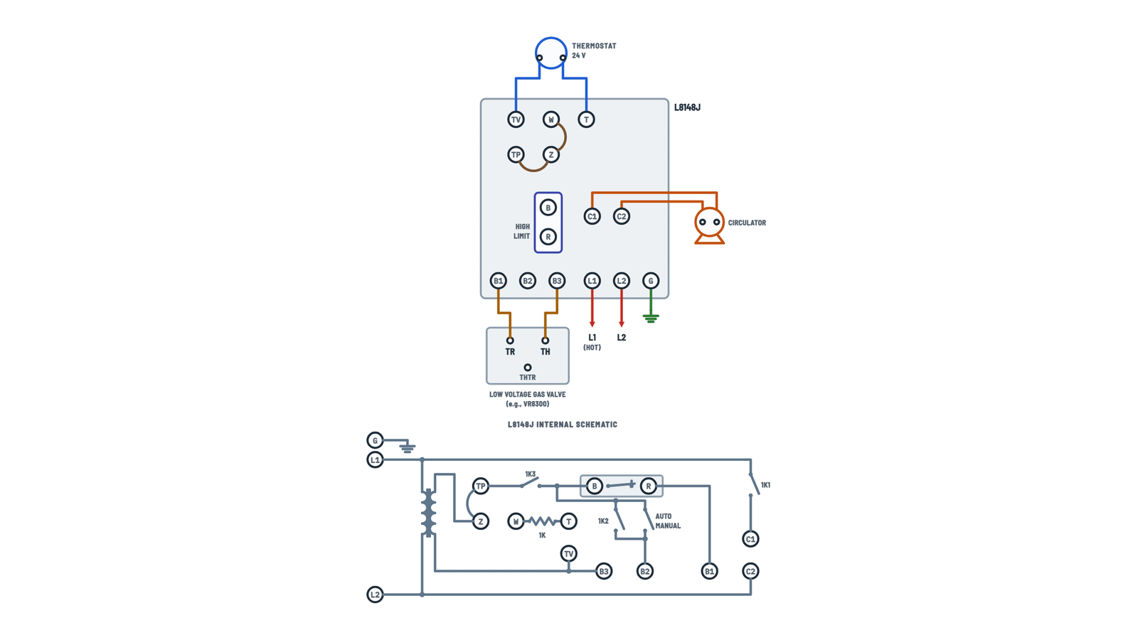
L8148J connections
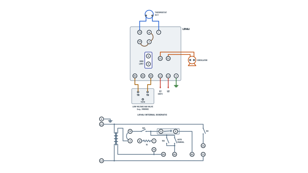
Thermostat, 24 V or millivoltage burner, circulator and power; below, the internal schematic in gray.
Terminals and components · 8
- Thermostat
- Jumpers
- L6006
- High limit
- Burner
- Powerpile
- Circulator
- Power
- Ground
What it does
Energizes the L8148J 1K relay: it starts the circulator and, if the water is below the high limit, the burner.
Setting
Set the thermostat heat anticipator at 0.2 A.
What it does
Carries 24 V from the internal transformer to the relay coil. Without it (and without an L6006), the L8148J won't respond to the thermostat.
What to do
With a millivoltage gas valve the W–Z jumper stays in place.
What to do
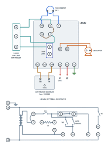
Remove the W–Z jumper when adding the L6006 low limit controller: its R–W contact takes its place.
What it does
Feeds 24 V from the transformer to the B1–B3 burner circuit (through contact 1K3 and the high limit).
What to do
Remove the TP–Z jumper: the millivoltage valve is powered by its own Powerpile generator.
How to connect it
- L6006 W to terminal W.
- L6006 R to terminal Z.
- L6006 B to the high limit B terminal.
What it does
- R–B closes when the water drops below the L6006 setting: it feeds 24 V to the high limit, bypassing the relay, so the burner keeps the boiler warm even without a call for heat.
- R–W closes when the water reaches the setting: it feeds the relay coil, so the circulator runs only with hot water.
24 V only
Use the L6006 only with the 24 V burner circuit (B1–B3). Remove the W–Z jumper.
What it does
It cuts only the burner: the circulator keeps running during the thermostat call for heat.
Setting
Follow the boiler manufacturer's recommendation. With the cover off, turn the dial until the setting is under the pointer; the dial stop can be adjusted.
Warning
Use the L8148J only in systems with a pressure relief valve.
How to connect it
B1 goes to TR and B3 to TH on the 24 V gas valve (e.g., VR8300). THTR and B2 stay empty. TP–Z and W–Z jumpers in place.
Ratings
0.8 A maximum at 24 V AC.
Caution
Never jumper or short terminals B1, B2 or B3: it burns out the L8148J transformer.
Terminal B1
B1 is a 1/4 in. tab terminal: use 18–22 gauge wire with a fully insulated flag receptacle connector.
How to connect it
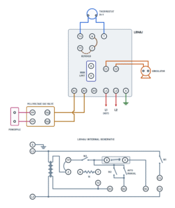
B1 goes to TH1 and B2 to TH2 on the millivoltage gas valve. B3 stays empty and the TP–Z jumper is removed.
Ratings
Millivoltage circuit: 0.25 A at 1/4 to 12 V DC.
AUTO-MANUAL switch
Millivolt models only. At MANUAL, the burner runs during a power failure until the high limit is reached (the circulator does not run). When power returns, set it back to AUTO.
Caution
Never jumper or short terminals B1, B2 or B3: it burns out the L8148J transformer.
Terminal B1
B1 is a 1/4 in. tab terminal: use 18–22 gauge wire with a fully insulated flag receptacle connector.
How to connect it
B1 goes to TR and B3 to TH on the 24 V gas valve (e.g., VR8300). THTR and B2 stay empty. TP–Z jumper in place.
Ratings
0.8 A maximum at 24 V AC.
Caution
Never jumper or short terminals B1, B2 or B3: it burns out the L8148J transformer.
Terminal B1
B1 is a 1/4 in. tab terminal: use 18–22 gauge wire with a fully insulated flag receptacle connector.
How to connect it
The two Powerpile generator leads go to the valve's PP terminals.
How to connect it
The two circulator leads go to C1 and C2. On a call for heat, contact 1K1 joins L1 to C1; C2 is tied to L2.
Contact rating
120 V AC 240 V AC Full load 7.4 A 3.7 A Locked rotor 44.4 A 22.7 A What it does
Feeds the internal transformer (24 V for the thermostat and burner) and, through the relay, the circulator.
Protection
Provide a disconnect means and overload protection as required.
How to wire it
- Copper wire only; the terminals accept wrap-around wiring only.
- Strip 7/16 in. and wrap the wire at least 3/4 of the way around the screw.
- Tighten until the wire contacts the plate, then one-half turn more (no push-type ratchet screwdriver).
What it does
Connects the L8148J metal case to earth ground with the grounding screw provided.
Required
The control case must be connected to earth ground.
Zoning with V8043F valves
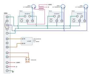
24 V thermostats, V8043F valves and one circulator; the third zone has its own transformer.
Terminals and components · 11
- Thermostats
- W (24 V)
- Valve motor
- Jumpers
- End switches
- Additional transformer
- Burner
- Circulator
- Power
- Ground
How to connect it
- One terminal of each thermostat goes to its valve's TR terminal.
- Zones 1 and 2: the other terminal goes to W on the L8148J.
- Zone 3: the other terminal goes to the additional transformer.
Capacity
The L8148J powers two V8043E or F zone valves, or only one when the ambient temperature exceeds 77 °F (25 °C). Use additional transformers for more valves.
Maximum load
1.4 A at 24 V AC; 1.2 A above 77 °F (25 °C) ambient.
How to connect it
TR goes to the zone thermostat. In zones 1 and 2, TH goes to TV on the L8148J and is jumpered to the end switch. In zone 3, TH goes to the additional transformer.
TH-TR
In this hookup the TH-TR terminal stays empty.
What it does
W–Z carries 24 V from the internal transformer to W. Each valve jumper joins TH to the end switch terminal that also goes to TV.
What it does
The end switch closes when the valve is fully open. It acts as the L8148J thermostat: one open zone is enough.
How to connect it
The zone 3 thermostat and its valve's TH terminal go to the 24 V secondary; the primary goes to L1 and L2. The end switch goes to T and TV like the other zones.
Protection
Provide a disconnect means and overload protection as required.
What it does
Feeds 24 V from the transformer to the B1–B3 burner circuit.
Millivoltage
With a millivoltage gas valve, wire it between B1 and B2 (TH1 and TH2) and remove the TP–Z jumper, as in the Complete tab.
Caution
Never jumper or short terminals B1, B2 or B3: it burns out the L8148J transformer.
Terminal B1
B1 is a 1/4 in. tab terminal: use 18–22 gauge wire with a fully insulated flag receptacle connector.
How to connect it
Its two leads go to C1 and C2; it starts when any zone calls for heat.
Contact rating
120 V AC 240 V AC Full load 7.4 A 3.7 A Locked rotor 44.4 A 22.7 A What it does
Feeds the internal transformer (24 V for the thermostat and burner) and, through the relay, the circulator.
Protection
Provide a disconnect means and overload protection as required.
How to wire it
- Copper wire only; the terminals accept wrap-around wiring only.
- Strip 7/16 in. and wrap the wire at least 3/4 of the way around the screw.
- Tighten until the wire contacts the plate, then one-half turn more (no push-type ratchet screwdriver).
What it does
Connects the L8148J metal case to earth ground with the grounding screw provided.
Required
The control case must be connected to earth ground.
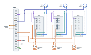
Zoning with R882C relays
Three zones with one circulator each, switched by R882C relays powered from the L8148J.
Terminals and components · 9
- Thermostats
- Z (24 V)
- Coils
- Heat call
- Circulators
- Jumper
- Burner
- Power
- Ground
How to connect it
One terminal of each thermostat goes to Z on the L8148J (all three in parallel) and the other to coil terminal B on its relay.
Capacity
The L8148J powers up to three R882C relays. Each additional group of up to three relays needs another transformer.
What it does
On a call for heat, the coil closes the upper contact (heat call to the L8148J) and the lower one (zone circulator).
Enclosure
The R882C comes with an NEC Class 1 enclosure.
What it does
Acts as the L8148J thermostat: with one zone calling, it fires the burner (if the water is below the high limit). N.C. stays empty.
How to connect it
C1 goes to each relay's lower N.O. contact; its COM. goes to the zone circulator, whose other lead returns to C2.
Contact rating
120 V AC 240 V AC Full load 7.4 A 3.7 A Locked rotor 44.4 A 22.7 A What it does
Joins W and Z so the internal transformer powers the L8148J relay and the zone thermostats.
L8148J
This hookup is drawn for the L8148E; the L8148J is the same but adds terminals TP and B3.
Depending on the burner
- 24 V gas valve: burner between B1 and B3, with the TP–Z and W–Z jumpers in place.
- Millivoltage (Powerpile) gas valve: burner between B1 and B2; remove the TP–Z jumper and leave W–Z in place.
Caution
Never jumper or short terminals B1, B2 or B3: it burns out the L8148J transformer.
Terminal B1
B1 is a 1/4 in. tab terminal: use 18–22 gauge wire with a fully insulated flag receptacle connector.
What it does
Feeds the internal transformer (24 V for the thermostat and burner) and, through the relay, the circulator.
Protection
Provide a disconnect means and overload protection as required.
How to wire it
- Copper wire only; the terminals accept wrap-around wiring only.
- Strip 7/16 in. and wrap the wire at least 3/4 of the way around the screw.
- Tighten until the wire contacts the plate, then one-half turn more (no push-type ratchet screwdriver).
What it does
Connects the L8148J metal case to earth ground with the grounding screw provided.
Required
The control case must be connected to earth ground.
About This Diagram
These diagrams are redrawn from page 11 of the Aquastat Relay L8148J manual, and we offer them completely free and in English. We have also categorized it in the Capacitors, Contactors & Relays (HVAC & Water Heating) section on Diagramverse, and it has been rated by 1 user with an average rating of 5.0. If you have any specific questions about the Honeywell Aquastat Relay L8148J Wiring Diagram, we suggest checking the Frequently Asked Questions (FAQs) section.
Printable Honeywell Aquastat Relay L8148J Wiring Diagrams


Wiring Instructions
Before you start
Identify which drawing matches your Honeywell Aquastat Relay L8148J system. Use the Complete tab for a single-zone boiler. Then pick the variant for your burner: 24 V gas valve if your gas valve has TR and TH terminals and runs on the control's transformer, Millivoltage if it is a Powerpile valve powered by a pilot generator (TH1, TH2 and PP terminals), or With L6006 low limit if you are adding a remote low limit controller to a 24 V gas valve system. Use the Zone valves tab if each zone has its own V8043F valve and thermostat. Use the R882C relays tab if each zone has its own circulator.
Gather a flat-blade screwdriver (not a push-type ratchet driver), wire strippers, a multimeter that reads AC volts, labels for tagging wires, and the heat-conductive compound if your immersion well is loose on the bulb. The terminals accept copper wire only and are wrap-around screw terminals. B1 is a 1/4 in. tab terminal. If you wire B1 with a tab connector, use 18 to 22 gauge wire with a fully insulated flag receptacle. The sources don't give a gauge for the other low-voltage terminals. Standard 18 AWG thermostat wire is common practice. Size the 120 V supply and circulator wiring to your circuit and local code.
This control is meant to be installed by a trained, experienced service technician. The boiler must have a pressure relief valve. Line-voltage work may need a permit, depending on where you live. If you are not comfortable working on 120 V boiler circuits and gas valves, hire a licensed professional.
Shut off power to the boiler at its disconnect and confirm with your meter that it is dead. If you are replacing an old control, tag every lead as you remove it, using the old control's cover insert as a guide.
Step-by-step wiring
- Mount the control on the immersion well. Push the bulb all the way to the bottom of the well, keep the loop of capillary tubing away from all electrical parts, and tighten the well clamp screw. Use the case's knockouts for 1/2 in. conduit.
- Prepare each wire: strip 7/16 in. of insulation, wrap it at least three-quarters of the way around the screw, tighten until it is snug against the screw and contact plate, then tighten one-half turn more.
- Connect the case ground to the grounding screw provided. Do this before you connect any other conductor.
- Set the jumpers for your variant. For a 24 V gas valve, leave both the W–Z jumper and the TP–Z jumper in place. For a millivoltage valve, remove TP–Z and leave W–Z in place. For the L6006 low limit, remove W–Z and leave TP–Z in place. The low limit works with the 24 V (B1–B3) burner circuit only.
- Wire the burner circuit. For a 24 V gas valve, run B1 to TR and B3 to TH on the valve, and leave B2 empty. For a millivoltage valve, run B1 to TH1 and B2 to TH2, and connect the Powerpile generator to the two PP terminals on the valve. If the old control had a screw terminal for B1, push the supplied tab-to-screw adapter onto the B1 tab and reuse the old wire end.
- If you are adding the L6006, connect it as shown: W to W, R to Z, and B to the high limit B.
- Wire the controls. For a single zone, run the 24 V thermostat to TV and T. For zone valves, run the end switches in parallel to T and TV, and power the thermostats and valves from W. Add the jumper between TH and the end switch on valves 1 and 2, and give the third valve its own 24 V transformer. For R882C relays, run the thermostats from Z to coil terminal B, the coil W to TV, and the upper contacts in parallel to TV and T.
- Connect the circulator to C1 and C2. With R882C relays, C1 feeds the lower N.O. contacts, each COM. feeds its zone circulator, and the circulators return to C2.
- Connect the 120 V supply last: hot to L1, neutral to L2. The supply needs a disconnect and overload protection.
Testing and start-up
Before you apply power, recheck every terminal against the drawing. Make sure nothing bridges B1, B2 or B3, and tug each wire to confirm it is tight. Set the thermostat heat anticipator to 0.2 A. Set the high limit dial to the boiler manufacturer's recommendation. On millivolt models, set the AUTO-MANUAL switch to AUTO.
Restore power. You should read about 120 V AC between L1 and L2. Raise the thermostat setting. The relay should pull in, the circulator should start, and the burner should light as long as the boiler water is below the high limit. Lower the thermostat setting: both the burner and the circulator should stop. If the boiler reaches the high limit during a call, the burner shuts off while the circulator keeps running. Watch the system through at least one complete cycle. In a zoned system, test each zone on its own.
Safety notes
- The case holds 120 V terminals next to the low-voltage ones. Disconnect power before you remove the cover, even to adjust the dial.
- Never jumper or short B1, B2 or B3: it burns out the internal transformer.
- Do not exceed the ratings: 7.4 A full load at 120 V for the circulator, 0.8 A at 24 V AC for a 24 V burner, and 0.25 A for a millivolt burner. The total 24 V load must not exceed 1.4 A, or 1.2 A above 77°F (25°C).
- Never run the boiler without a working pressure relief valve.
Troubleshooting
| Symptom | Probable Cause | What to Check |
|---|---|---|
| Circulator runs on a call for heat, but the burner never lights (24 V gas valve) | TP–Z jumper missing, or the gas valve is wired to B1–B2 instead of B1–B3 | Confirm the TP–Z jumper is in place and the valve wires go to B1 and B3. With the thermostat calling, measure about 24 V AC across TR and TH at the gas valve. |
| Millivolt gas valve won't open even though the pilot is lit | Valve wired to B3, or the TP–Z jumper was left in | Move the valve wires to B1 (to TH1) and B2 (to TH2), and remove the TP–Z jumper. Check that the Powerpile leads are tight on both PP terminals. |
| Nothing works: no burner and no circulator, and the thermostat seems dead | Transformer burned out by a short across B1, B2 or B3, or no 120 V at L1–L2 | Measure 120 V AC between L1 and L2. If it is present but there is no 24 V on the control circuit, look for a shorted burner wire or a jumper across the B terminals. A burned-out transformer means replacing the control. |
| After I added the low limit, the system won't respond to the thermostat | L6006 miswired, or the W–Z jumper is still in place alongside it | Remove the W–Z jumper. Check the L6006 connections: W to W, R to Z, and B to the high limit B. Use the low limit only with a B1–B3 burner circuit. |
| Boiler won't fire unless the low limit is connected, or it stops working when I disconnect it | W–Z jumper removed without a low limit controller in its place | Reinstall the W–Z jumper between W and Z whenever no L6006 is connected. |
| Zone valves open, but the boiler and pump never start | End switches not wired in parallel to T and TV, or a loose end-switch lead | With one valve fully open, check for continuity across that valve's end switch, and confirm one lead of each switch goes to T and the other to TV. |
| Zone valves open slowly or chatter, or the control works intermittently on hot days | 24 V transformer overloaded by too many valves | Power no more than two V8043 valves from the L8148J, and only one above 77°F (25°C). Move additional valves to their own transformer. |
| Burner short-cycles, or the thermostat overshoots or undershoots the setpoint | Thermostat heat anticipator set wrong | Set the thermostat's heat anticipator to 0.2 A. |
| Burner runs, but the circulator never starts | Loose or misplaced circulator lead, or the neutral is missing at L2 | With the thermostat calling, measure 120 V AC at the circulator leads. Check that C1 and C2 are tight and that L2 is connected to the supply neutral. |
| I get a tingle or shock from the boiler or control case | Case not grounded | Turn off the power. Connect an equipment ground conductor to the grounding screw provided, and check continuity from the case to ground. |
| Wire keeps coming loose from a terminal, or a terminal gets hot | Wire wrapped the wrong way, not enough wrap, or aluminum wire used | Use copper wire only. Strip 7/16 in., wrap at least three-quarters of the way around the screw, tighten until snug, then tighten one-half turn more. |
| Burner runs nonstop on a millivolt system and ignores the thermostat | AUTO-MANUAL switch left in MANUAL | Set the switch back to AUTO. MANUAL is only for running the burner during a power failure. |