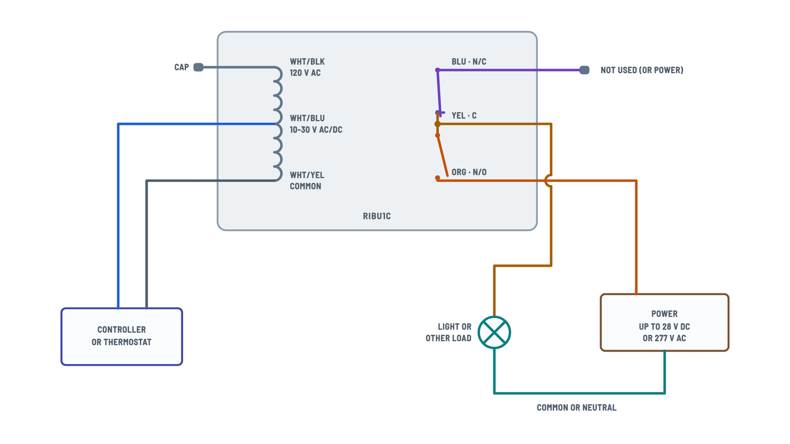
RIBU1C Enclosed Relay 10Amp Wiring Diagram
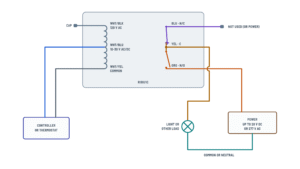
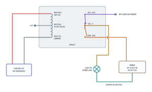
Typical RIBU1C hookup
Choose the coil input; tap any wire to see how it connects.
Terminals and components · 8
- 10-30 V coil
- 120 V coil
- Coil common
- C
- N/O
- N/C
- Load
Coil data
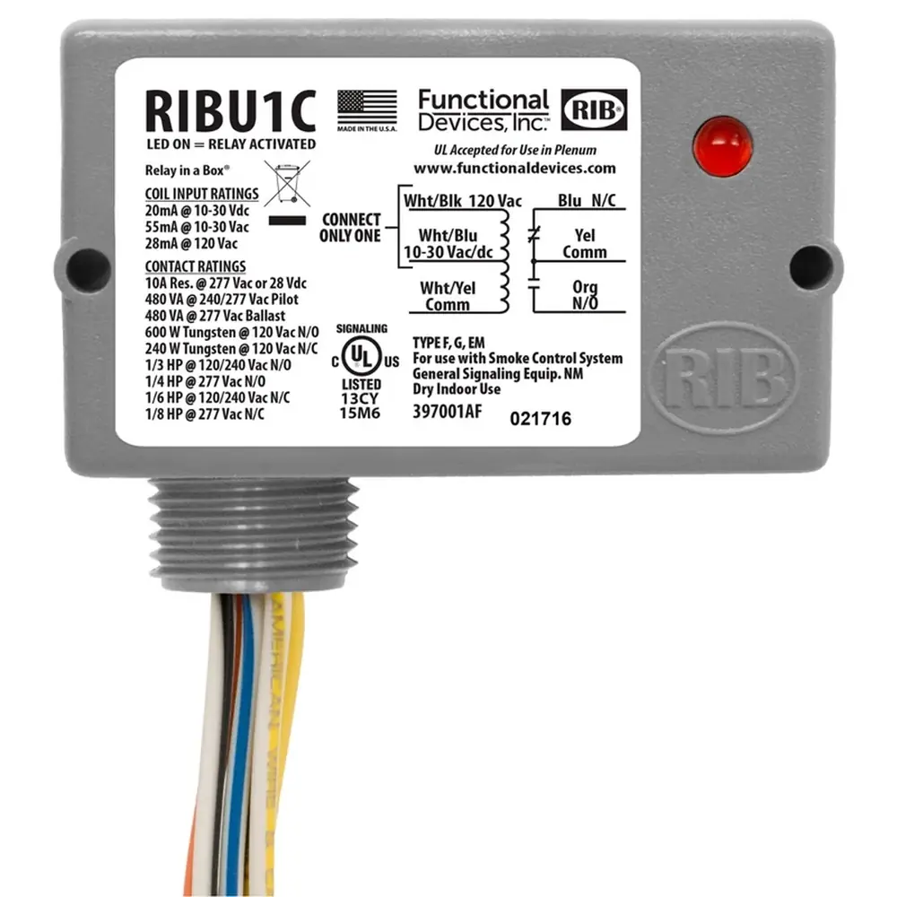
Voltage Current 12 V AC 35 mA 24 V AC 46 mA 12 V DC 15 mA 24 V DC 18 mA Caution
With this input, cap the white/black 120 V wire: don't leave it loose.
Caution
With this input, cap the white/blue 10-30 V wire. Never apply 120 V to the white/blue.
How to connect it
Always used, with either coil input.
Operation
The LED is on when the coil is energized. It pulls in at 9 V AC / 10 V DC and drops out below 2.1 V AC / 2.8 V DC.
Typical use
Lets a controller or thermostat control any load within the contact rating.
How to connect it
Run the yellow to one side of the load; the other side of the load goes to the source common or neutral.
Rating
Load Max (N/O) Resistive 10 A @ 277 V AC · 10 A @ 28 V DC Pilot duty 480 VA @ 240-277 V AC Tungsten 600 W @ 120 V AC Motor 1/3 HP @ 120-240 V AC · 1/4 HP @ 277 V AC Caution
Not rated for electronic ballasts.
When to use it
If the load must run while the coil is off, bring power to the blue instead of the orange.
Rating (N/C)
Load Max Tungsten 240 W @ 120 V AC Motor 1/6 HP @ 120-240 V AC · 1/8 HP @ 277 V AC Caution
The load supply is separate from the coil voltage; turn both off before wiring.
About This Diagram
This diagram is redrawn from page 1 of the RIBU1C Enclosed Relay 10Amp manual, and we offer it completely free and in English. We have also categorized it in the Control Relays & Timers (Motors & Industrial) section on Diagramverse, and it has been rated by 1 user with an average rating of 5.0. If you have any specific questions about the RIBU1C Enclosed Relay 10Amp Wiring Diagram, we suggest checking the Frequently Asked Questions (FAQs) section.
Printable RIBU1C 10Amp Wiring Diagrams
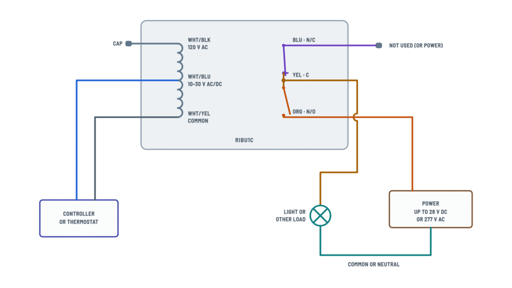
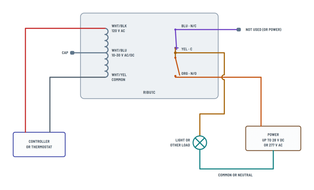
Wiring Instructions
Before you start
The RIBU1C 10Amp lets a low-power controller or thermostat switch a separate load. It has two separate circuits, so plan each one before you begin. The coil side uses Wht/Blu, Wht/Blk and Wht/Yel. The contact side uses Yel (C), Org (N/O) and Blu (N/C).
Pick the diagram variant that matches the control voltage your controller supplies:
- 10-30 V coil: use this variant if the controller or thermostat puts out 10-30 V AC or DC, for example a 24 V AC thermostat or a 12 or 24 V DC building automation output.
- 120 V AC coil: use this variant if the control signal is 120 V AC.
Use only one coil input, never both. Before you buy or wire anything, confirm that the load is within the contact ratings. The contacts handle 10 A resistive at up to 277 V AC or 28 V DC. Motor, tungsten and ballast loads have lower ratings, and the N/C contact has lower tungsten and horsepower ratings than the N/O contact. The relay is not rated for electronic ballasts.
Tools and materials: a non-contact voltage tester, a multimeter that reads AC and DC volts and continuity, wire strippers, wire connectors rated for the conductor sizes and count you are joining, and a junction box with a 1/2 inch knockout for the 0.50 inch NPT hub. The relay's leads are 16 inches long and rated 600 V. Size the field conductors of the load circuit for the load current and the overcurrent device that protects that circuit. If you are unsure, follow your local code or ask an electrician.
Isolation: turn off and lock out the breaker for the load circuit. Also turn off the controller's power, or its transformer. A 120 V AC control circuit is line voltage, so treat it that way.
Line-voltage work, new circuits, and any installation in a fire alarm system (the RIBU1C-RD version) should be done by a licensed electrician. Many jurisdictions require a permit for this work.
Step-by-step wiring
- Mount the relay by its 0.50 inch NPT hub through a knockout in a junction box, so all leads and splices end up inside the box. Use the standard grey housing indoors in dry locations. Use the RIBU1C-N4 where you need a NEMA 4 housing.
- Confirm that power is off at both the controller and the load circuit, using your tester on the conductors you will touch.
- Connect Wht/Yel (coil common) to the controller's common, or to neutral for a 120 V AC control circuit.
- Connect the coil input that matches your variant to the controller's switched output. Use Wht/Blu for 10-30 V AC/DC or Wht/Blk for 120 V AC.
- Cap the unused coil lead on its own with a wire connector. Do not leave its bare end loose in the box.
- Connect Org (N/O) to the hot side of the load power source.
- Connect Yel (C) to the load. This is the switched leg out to the light or other load.
- Connect the load's other side to the source neutral or common, not to the relay.
- If you are not using Blu (N/C), cap it individually. Use Blu only if the load should run while the coil is off, and then check its lower tungsten and horsepower ratings.
- Tug-test every splice. Keep the low-voltage control wiring separated from the line-voltage load wiring, as your local code requires, then close the box.
Testing and start-up
Restore power to the controller first, with the load breaker still off.
- Command the controller on. The LED on the relay should light, because LED on means the relay is activated.
- Measure the voltage between the coil input you used and Wht/Yel. It should be at least the pull-in voltage of 9 V AC or 10 V DC on the low-voltage input, or close to 120 V AC on Wht/Blk.
- Command the controller off. The LED should go out, and the coil voltage should fall below the drop-out voltage of 2.1 V AC or 2.8 V DC.
- With the load still unpowered, check continuity. Yel to Org should close when the coil is on. Yel to Blu should close when the coil is off.
- Turn the load breaker on and cycle the controller a few times. The load should follow the command, and the relay should switch cleanly with no buzzing.
Safety notes
- The load contacts can carry up to 277 V AC. Even when the coil is off, the Org lead (and the Blu lead, if used) stays live whenever the load breaker is on.
- On the 120 V AC coil variant, the coil circuit is also line voltage. Isolate it separately from the load circuit.
- Never exceed 10 A on the contacts. For motors, tungsten lamps and ballasts, use the matching lower rating, and do not use the relay with electronic ballasts.
- Install the relay only within -30 to 140°F and 5 to 95% humidity, noncondensing, and choose a housing rated for the location.
- The relay has no manual override switch. To test the load without the controller, use a proper control-voltage source, not a jumper across live contacts.
Troubleshooting
| Symptom | Probable Cause | What to Check |
|---|---|---|
| The LED never lights and the load never turns on | No control voltage at the coil, the wrong coil lead is used, or Wht/Yel is not connected to the controller common | Measure between the coil input you used and Wht/Yel while the controller is calling. You should read 10-30 V on Wht/Blu, or about 120 V AC on Wht/Blk. If you read nothing, check the controller output and the Wht/Yel return. |
| The relay buzzes, chatters or clicks on and off | Control voltage below pull-in, or an overloaded or undersized control transformer | Measure the coil voltage while the relay is energized. It must stay above 9 V AC or 10 V DC on the 10-30 V input. Check that the transformer can supply the coil current, for example about 46 mA at 24 V AC, plus its other loads. |
| The LED stays on, or the relay will not release, when the controller turns off | Leakage voltage from a solid-state or triac controller output | With the controller commanded off, measure across the coil input and Wht/Yel. Anything above 2.1 V AC or 2.8 V DC can hold the relay in. Use a dry-contact output, or ask the controller maker how to handle leakage. |
| The load runs when it should be off and stops when it should run | Load supply connected to Blu (N/C) instead of Org (N/O) | Turn off power and move the load supply from Blu to Org. Then confirm that Yel to Org shows continuity only while the LED is on. |
| The relay clicks and the LED lights, but the load does nothing | No supply on Org, Yel not connected to the load, or the load not returned to neutral or common | With the coil energized, measure from Yel to the source neutral or common. You should read the full supply voltage. If you do, trace the load's return conductor. If you do not, check the Org feed and its breaker. |
| The breaker trips the moment the relay closes | Yel or Org connected to neutral, common or ground instead of to the load, which creates a dead short through the contacts | Turn off power and verify the path: hot to Org, Yel to the load, and the load to neutral. Check for continuity from Yel to neutral with the load disconnected. There should be none. |
| The relay died right after power-up on a 120 V control circuit | 120 V AC applied to the Wht/Blu low-voltage input | Confirm the controller's output voltage. The 120 V AC signal must go to Wht/Blk. If the relay no longer responds, replace it and rewire it correctly. |
| The load stays on permanently, or the contacts fail early | Load beyond the contact rating, such as a large motor, heavy tungsten load or electronic ballast | Compare the load nameplate with the ratings: 10 A resistive, 1/3 HP at 120-240 V AC on N/O, 600 W tungsten at 120 V AC on N/O, and no electronic ballasts. Use a contactor for larger loads. |
| A breaker or the controller fuse trips at random | The unused coil lead or Blu lead is uncapped and touching metal or another conductor in the box | Turn off power, open the box, and cap each unused lead individually with a wire connector. |
| The load works intermittently or flickers | Loose splice on the stranded relay leads | Turn off power, then remake and tug-test each connection. Use connectors sized for the conductor combination. |