
Minotaur MSR127TP Monitoring Safety Relay Wiring Diagram
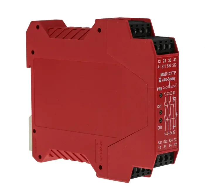
Minotaur MSR127TP Monitoring Safety Relay Wiring Diagram
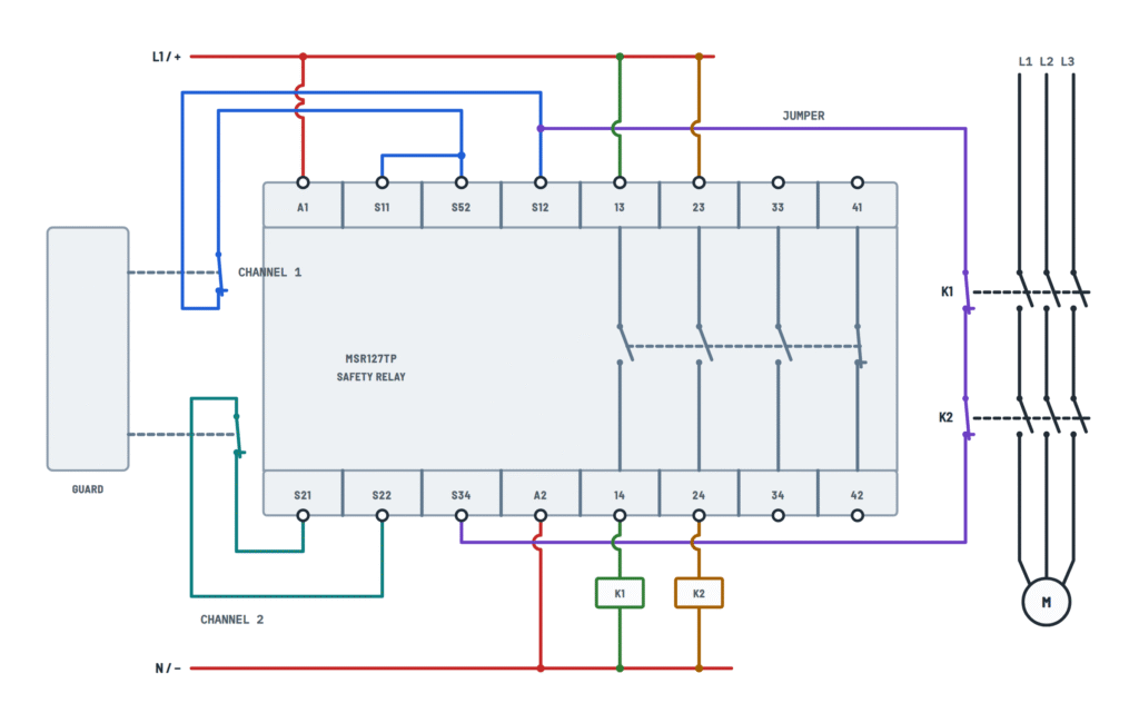
Two-channel guard with contactors
Guard with two contacts, two contactors with feedback and a three-phase motor.
Terminals and components · 9
- Power
- Channel 1
- Channel 2
- Start
- 13-14
- 23-24
- Load
Version voltage
The voltage is on the relay label; 0.85 to 1.1 times the rated value is allowed. When powered, the PWR indicator turns on.
With 24V DC
If you use external 24V DC signals on the inputs, the negative must go to S21.
4-wire connection
With both channels separate (S11-S12 and S21-S22), the relay detects shorts between channels: up to PLe. A cross fault makes PWR flash and the fault must be reset.
Other connections
Single channel, 3-wire or light curtain: see the “Inputs” tab.
Manual start
The outputs turn on when you press start with the inputs closed. The TP does not monitor the button edge: if it stays pressed, it acts as automatic start.
Feedback
If a contactor welds, its N.C. contact does not close and the relay will not start again.
Automatic start
The outputs turn on by themselves as soon as the inputs close. If they are closed at power-up, the relay starts right away (after 1 s).
Feedback
If a contactor welds, its N.C. contact does not close and the relay will not start again.
Fuse
Protect each output with an external 6 A slow-blow or 10 A fast-acting fuse.
CH1 indicator
Lights green when the channel 1 output is on.
CH2 indicator
Lights green when the channel 2 output is on.
Linked contacts
Use contactors whose N.C. auxiliary contacts are mechanically linked to the main contacts, so the feedback is reliable.
Not a safety output
Do not use 41-42 to switch a hazardous load: it is only a status signal.
Safety input connections
The four ways to wire S11, S52, S12, S21 and S22 and the maximum safety level of each.
Terminals and components · 3
- Channel 1
- Channel 2
- Jumpers
- OSSD
Single channel
No short-circuit detection: a bare wire touching another can defeat the stop. Low-risk applications only.
Cross fault detection
With 4 wires the relay detects a short between channels; the fault must then be reset (open the inputs or cycle power).
To reach PLe
Separate the channels with the 4-wire connection.
Cross faults
With 24V DC signals the relay does not monitor cross faults: the curtain detects them.
About This Diagram
These diagrams are redrawn from pages 2–3 of the Minotaur MSR127TP Monitoring Safety Relay manual, and we offer them completely free and in English. We have also categorized it in the Control Relays & Timers (Motors & Industrial) section on Diagramverse, and it has been rated by 1 user with an average rating of 5.0. If you have any specific questions about the Minotaur MSR127TP Monitoring Safety Relay Wiring Diagram, we suggest checking the Frequently Asked Questions (FAQs) section.
Printable Minotaur MSR127TP Wiring Diagrams





Wiring Instructions
Before you start
The Minotaur MSR127TP is part of your machine's safety-related control system. Only trained, authorized personnel should install, commission or modify it. Before you wire anything, do a risk assessment to confirm the relay and the input arrangement you choose reach the required performance level. In most jurisdictions, safety circuits on commercial or industrial machinery have to be designed and signed off by a qualified person, so check your local requirements.
Pick the drawing that matches your installation. The Complete tab shows a two-channel guard driving contactors K1 and K2. Use Manual start if an operator has to press a button after closing the guard, or Automatic if the machine restarts as soon as the guard closes. The Inputs tab shows the four ways to connect the safety device: 1 channel, 2 ch., 3 wires, 2 ch., 4 wires, or 24V DC curtain for a light curtain with PNP outputs.
- Tools: insulated screwdrivers, a torque screwdriver that can reach 5 to 7 lb·in, a multimeter with continuity and resistance ranges, a wire stripper and ferrules.
- Wire: copper rated 60/75 °C (140/167 °F), 24 to 12 AWG.
- Mounting: a 35 mm DIN rail inside an enclosure rated IP54 or better.
- Protection: an external fuse for the output circuit, either 6 A slow-blow or 10 A fast-acting.
- Contactors: K1 and K2 must each have an N.C. feedback contact.
Read the rating label to confirm the supply version: 24V AC/DC, 115V AC or 230V AC. Lock out and tag out every source that feeds the panel, including any separate supply on the output contacts. Then confirm with your meter that no voltage is present.
Step-by-step wiring
- Mount the relay on the DIN rail. On P versions the terminal blocks unplug: insert a screwdriver and lever them out slowly, so you can pre-wire them on the bench.
- Connect the supply. Wire A1 to L1 (or +24V) and A2 to N (or 0V). Under load, the supply must stay between 0.85 and 1.1 times the rated voltage.
- Wire the safety input for your variant. 2 ch., 4 wires: jumper S11 to S52, connect the channel 1 N.C. contact between S52 and S12, and the channel 2 N.C. contact between S21 and S22. 2 ch., 3 wires: run one common from S11, with one N.C. contact to S52 and the other to S12. 1 channel: connect the contact between S11 and S52 and jumper S52 to S12. With either of these last two, jumper S21 to S22 if the second channel doesn't use them.
- For a 24V DC curtain, connect OSSD1 to S52 and OSSD2 to S12. Connect the curtain's 0V to S21 as well as to its own power supply, and leave S11 free.
- Keep each input loop at 110 Ω or less, counting the full cable length and every contact in the loop.
- Wire the start and feedback loop from S12 to S34. Wire the N.C. feedback contacts of K1 and K2 in series with either an N.O. start button (Manual start) or a jumper (Automatic). Never leave the feedback contacts out.
- Feed 13 and 23 from L1 through the external fuse. Connect 14 to the K1 coil and 24 to the K2 coil, and return both coils to N. Stay within 5 A at 250V AC (AC-15) or 3 A at 24V DC (DC-13). As general good practice, fit surge suppressors on the contactor coils to extend contact life.
- Wire the main contacts of K1 and K2 in series on L1, L2 and L3 to the motor, so either contactor alone can stop it.
- Leave 33-34 spare or use it for a third safety load. Wire 41-42 only to a PLC input or a pilot light.
- Torque every terminal screw to 0.6 to 0.8 N·m (5 to 7 lb·in), then tug each wire to make sure it is held.
Testing and start-up
With the power still off, use continuity mode to check that each input channel opens when you open the guard or press the E-stop. With the guard closed, measure the resistance of each loop and confirm it is under 110 Ω. Check that S12-S34 closes only while the start button is pressed (or always, with the jumper) and both contactors are released.
Restore power. The green PWR light should come on, and the relay is ready after about 1 s. Close the guard and press start, or let it start on its own in Automatic. CH1 and CH2 should light, K1 and K2 should pull in, and 41-42 should open. Then open the guard: the outputs must drop within 15 ms, both CH lights must go out and the motor must stop.
Next, test each channel on its own by opening one contact at a time. The outputs must drop every time. To test the feedback loop, isolate the power, lift one feedback wire from the S12-S34 loop and power up again. The relay must refuse to start. Reconnect the wire when you're done. Repeat the full functional test at least once every six months and record the results.
Safety notes
- On the 115V AC and 230V AC versions, terminals A1 and A2 carry mains voltage. The output contacts can carry mains voltage on any version. The terminals are only IP20, so never work on them live.
- The output circuit may be fed from a different source than the relay supply. Isolate both before you touch the terminals.
- Automatic start restarts the machine as soon as the inputs close. Use it only where your risk assessment shows that nobody can be inside the hazard zone when the guard closes.
- 41-42 is a non-safety auxiliary contact. Never use it in the safety function.
- The relay is not repairable. If it is damaged or keeps faulting, replace it before the machine runs again. Never bypass or jumper out a safety input to keep production going.
Troubleshooting
| Symptom | Probable Cause | What to Check |
|---|---|---|
| Nothing lights up, not even PWR | No supply at A1-A2, wrong voltage version, or a loose supply wire | Measure between A1 and A2. It must be between 0.85 and 1.1 times the voltage on the rating label. Check that A1 goes to L1 or +24V and A2 to N or 0V, and retorque to 5 to 7 lb·in. |
| PWR is on but CH1 and CH2 never light, even with the guard closed | The start and feedback loop is open: K1 or K2 is wired on an N.O. contact instead of N.C., or the jumper is missing in Automatic mode | With the power off, check continuity from S12 to S34 with both contactors released (and the button pressed for manual start). It must read closed. |
| The PWR light is flashing green | Cross-loop fault: the two channels are shorted together, wires are swapped between S52/S12 and S21/S22, or a cable is damaged | With the power off, check there is no continuity between the channel 1 terminals (S52, S12) and the channel 2 terminals (S21, S22). Repair the wiring, then cycle the safety input or the power to clear the fault. |
| The light curtain shows clear but the relay won't enable | Curtain 0V not connected to S21, S11 wired by mistake, or OSSDs on the wrong terminals | With the curtain clear, measure about 24V DC from S52 to S21 and from S12 to S21. Leave S11 free. |
| The guard is closed but the relay won't start with 4-wire wiring | The S11-S52 jumper is missing, or a contact is on the wrong terminal pair | Fit the short jumper between S11 and S52. Confirm the channel 1 contact is between S52 and S12 and channel 2 is between S21 and S22. |
| A single-channel E-stop never enables the outputs | The S52-S12 or S21-S22 jumper is missing | Jumper S52 to S12 and S21 to S22. The E-stop contact goes between S11 and S52 only. |
| The relay drops out at random, especially on long cable runs | Loop resistance too high, a loose terminal, or undersized wire | Measure each closed loop. It must be 110 Ω or less. Use heavier wire within the 24 to 12 AWG range and retorque every screw. |
| The machine restarts by itself when the guard closes | Automatic variant wired (jumper in S12-S34) where manual start was intended | Replace the jumper with an N.O. start button in series with the K1 and K2 N.C. contacts. |
| CH1 and CH2 are lit but the contactors don't pull in | Blown external fuse, 13 or 23 not fed, or the coil return to N is open | Measure voltage at 14 and 24 with respect to N, check the fuse (6 A slow-blow or 10 A fast-acting), and check the coil return wiring. |
| The PLC or pilot light shows the opposite status | 41-42 treated as an N.O. contact | 41-42 is closed while the safety outputs are off and open while they are on. Invert the logic in the PLC, or wire the pilot light to suit. |


