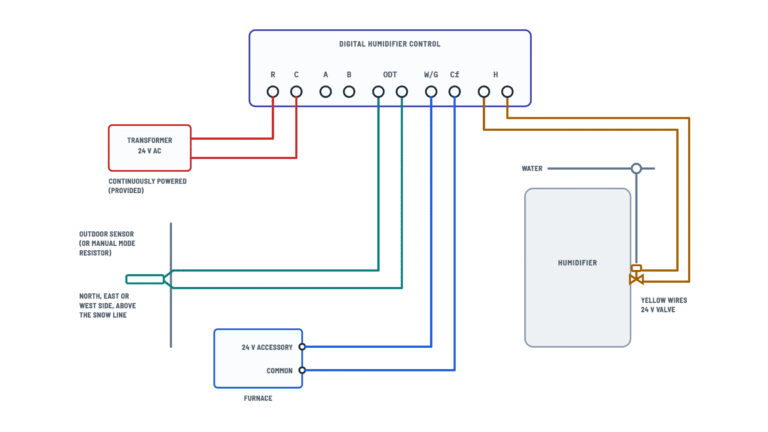
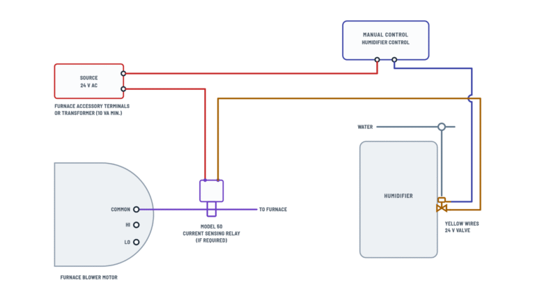
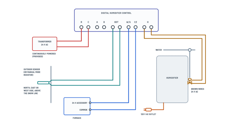
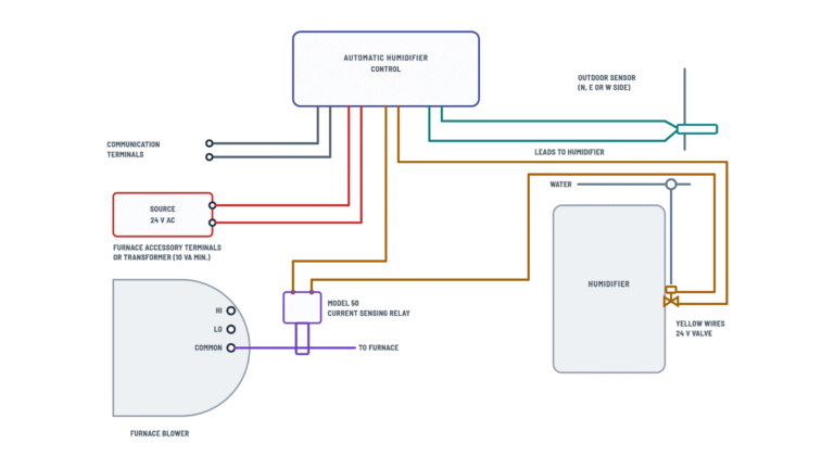
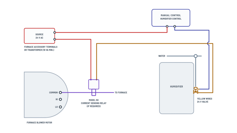
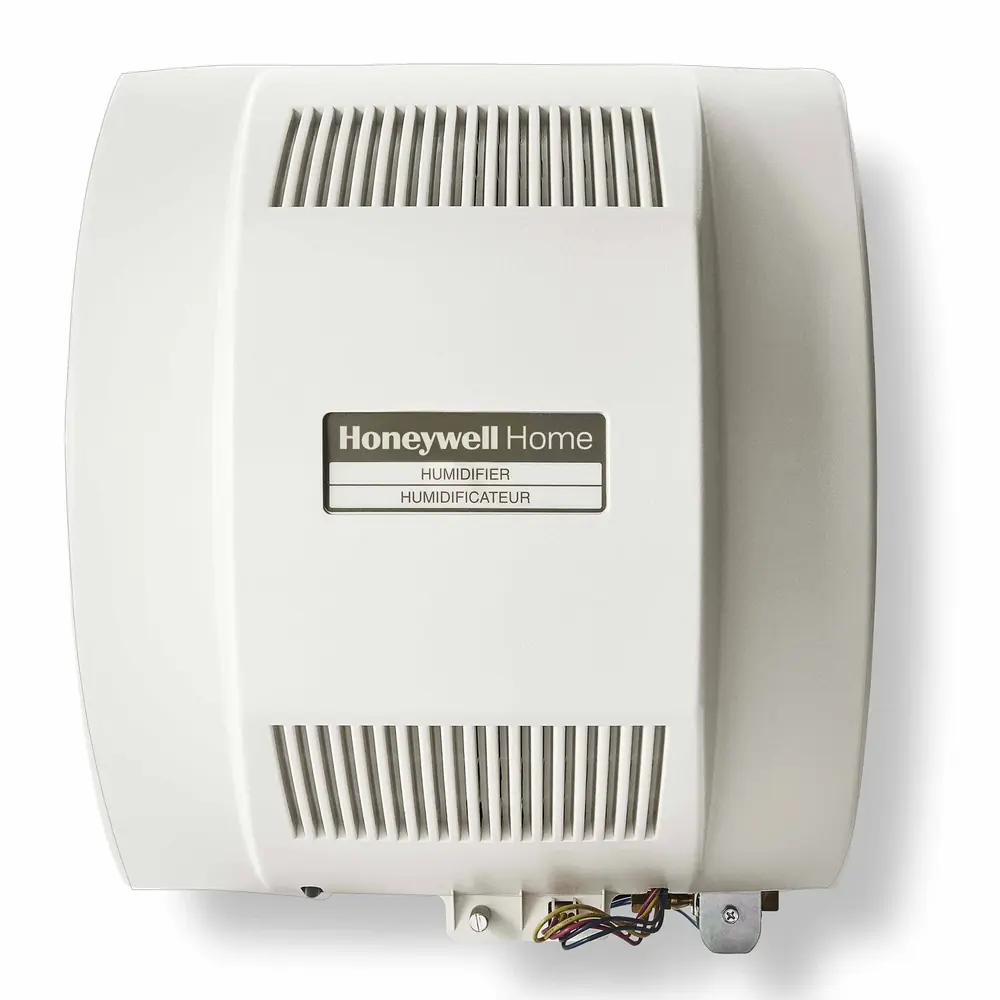
Honeywell HE360 Humidifier Wiring Diagram
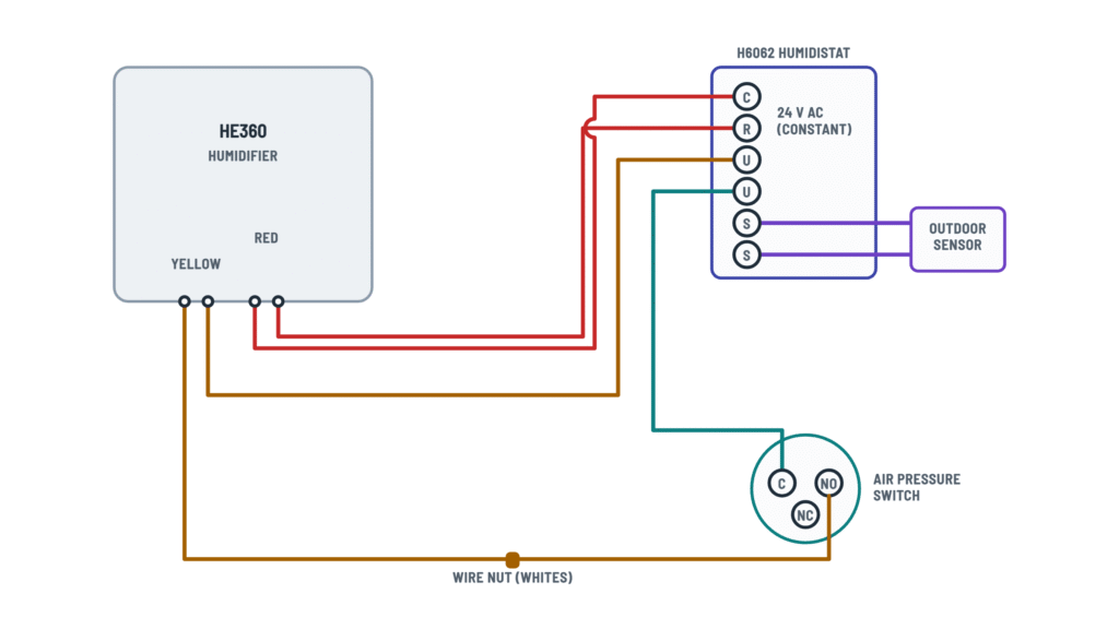
HE360 control wiring
Humidifier, humidistat and air switch; the red and white wires of each bundle can be swapped.
Terminals and components · 5
- Red wires
- Valve
- Air switch
- Humidistat
- Outdoor sensor
How to connect it
- At the humidifier, connect the two red wires to the red and white wires of bundle 1.
- At the humidistat, connect the red and white wires of bundle 1 to R and C (polarity doesn't matter).
What to do
With the H8908 humidistat, the humidifier red wires are not used: insulate them.
How to connect it
- At the humidifier, connect the two yellow wires to the red and white wires of bundle 2.
- At the humidistat, the red wire of bundle 2 goes to the upper U terminal.
- The white wire of bundle 2 is wire-nutted to the white wire of bundle 3 (going to the pressure switch).
How to connect it
- At the humidifier, connect the black and white conductors of bundle 1 to the two yellow wires.
- At the humidistat, connect both black conductors to its two terminals and wire-nut the two white conductors.
Important
Use this wiring diagram, not the one supplied with the humidistat instructions.
H6062 terminals
Terminal Goes to R · C Red wires (constant 24 V AC) U (upper) Bundle 2 red (valve) U (lower) Bundle 3 red (pressure switch) S · S Outdoor sensor What it does
The H8908 is a two-terminal humidity control: its two black conductors are in series with the valve and the sail switch.
How to connect it
- At the humidistat, the red wire of bundle 3 goes to the lower U terminal.
- At the pressure switch, the red and white wires of bundle 3 go to C and NO. NC is not used.
Important
The furnace blower must be on to activate the humidifier.
How to connect it
At the sail switch, the black and white conductors of bundle 2 go to COM and NO. NC is not used. The humidistat and sail switch can be wired in any order.
How to connect it
Connect the two outdoor sensor wires to the S terminals.
About This Diagram
This diagram is redrawn from page 11 of the Honeywell HE360 Humidifier manual, and we offer it completely free and in English. We have also categorized it in the Humidifiers (HVAC & Water Heating) section on Diagramverse, and it has been rated by 1 user with an average rating of 5.0. If you have any specific questions about the Honeywell HE360 Humidifier Wiring Diagram, we suggest checking the Frequently Asked Questions (FAQs) section.
Printable Honeywell HE360 Wiring Diagrams


Wiring Instructions
Before you start
First, find out which variant of Honeywell HE360 you have. Current HE360A1075 and HE360D1075 packages come with an H6062 digital humidistat and an air pressure switch. For these, use the H6062 + pressure variant. Older HE360 installation kits came with an H8908 dial humidistat and a sail switch. For these, use H8908 + sail. The wiring is different: the H6062 needs constant 24 V AC on its R and C terminals, but the H8908 is just a contact in series with the valve. Wire from this HE360 drawing, not from the generic diagram packed with the humidistat.
Tools: screwdriver, wire stripper, drill, punch or awl, tin snips, level, gloves, safety glasses and a multimeter that reads AC voltage. Materials: 18 gauge two-strand thermostat wire and wire nuts (four are included). For the H6062 + pressure layout, plan on three two-strand bundles. Two run from the humidifier to the humidistat, and one runs from the humidistat to the pressure switch. Measure each run and leave extra wire at both ends.
The humidifier plugs into a 120 V, 60 Hz outlet and draws 0.7 A. If there's no outlet within reach of the cord, have a licensed electrician install one. That work usually needs a permit, so check with your local authority. Before you wire anything, unplug the humidifier and turn off the furnace or air handler at its circuit breaker.
Mount the components first. Mount the pressure switch vertically with its pressure connectors facing down. Run the supply duct tubing to the + port and the return duct tubing to the – port. Install the sail switch in the cold air return. Keep only the spring that matches the airflow direction, or remove both springs for horizontal airflow. Mount the humidistat on the return plenum at least 8 in. upstream of the humidifier, or on a wall in the living space.
Step-by-step wiring: H6062 + pressure
- Pull the three bundles and label them 1, 2 and 3 at both ends. Labeling prevents the most common mix-up: swapping the power bundle and the valve bundle.
- At the humidifier, splice the two red wires to the red and white conductors of bundle 1 with wire nuts.
- At the humidifier, splice the two yellow wires (solenoid valve) to the red and white conductors of bundle 2.
- At the humidistat, land bundle 1 on R and C. Either color can go on either terminal.
- Land the red conductor of bundle 2 on the upper U terminal.
- Join the white conductor of bundle 2 to the white conductor of bundle 3 with a wire nut. This splice carries the valve circuit on to the air switch.
- Land the red conductor of bundle 3 on the lower U terminal.
- At the pressure switch, connect the red and white conductors of bundle 3 to C and NO. Leave NC empty.
- If you use the optional outdoor sensor, wire it to the two S terminals.
Step-by-step wiring: H8908 + sail
- Run one two-strand cable from the humidifier to the humidistat and another from the humidistat to the sail switch. You can wire the humidistat and the sail switch in either order.
- At the humidifier, splice the black and white conductors to the two yellow wires. The red wires are not used. Cap each one separately so the bare ends can't touch anything.
- At the humidistat, connect both black conductors to its two terminals, and join the two white conductors with a wire nut.
- At the sail switch, connect black to COM and white to NO. Leave NC empty. Snap the cover on after wiring.
Whichever variant you have, tug each wire nut to make sure it holds, and tighten the terminal screws onto bare copper, not insulation. Secure the cable so it stays clear of hot flue pipes, sharp duct edges and the drain line.
Testing and start-up
- Before power-up, confirm the humidifier is level, the feed line has no kinks, the drain line slopes continuously down to the floor drain, and the internal hose is connected to the water distribution tray.
- Plug in the humidifier, turn the furnace breaker back on and open the water shut-off valve.
- H6062 + pressure only: measure across R and C. You should read about 24 V AC at all times, whether or not the blower is running.
- Turn the H6062 all the way up (Humidity Boost should appear), or set the H8908 to On. Then set the thermostat 10°F above room temperature so the furnace and blower start.
- With the blower running, you should hear the solenoid valve click, and water should flow out of the drain hose shortly after. With the blower off, the valve must stay closed even when the humidistat is calling.
- Check every water joint for leaks. Then return the thermostat and humidistat to comfortable settings for automatic operation.
Safety notes
- The cord and outlet carry 120 V. Unplug the humidifier, and shut off its water, before you remove the cover or touch the wiring.
- The control wiring is low-voltage 24 V AC, but it still matters. If the two red wires or R and C touch, they short the 24 V supply. If you put 24 V on the U terminals, you can damage the humidistat.
- Don't cut or drill into the A-coil, the wiring or any other air conditioning or electrical accessory. Wear gloves and safety glasses: cut duct edges are sharp.
- Keep wire nut splices dry and away from the solenoid valve and drain fittings. Respect the temperature limits: 32°F to 160°F around the humidifier, and -40°F to 190°F for the pressure switch.
- All wiring must comply with your local codes.
Troubleshooting
| Symptom | Probable Cause | What to Check |
|---|---|---|
| H6062 never calls for humidity and there's no 24 V at R and C | Humidifier unplugged, outlet dead, or a loose splice between the humidifier red wires and bundle 1 | Check the outlet for 120 V. Then measure across R and C. You should read about 24 V AC with the humidifier plugged in. If you don't, redo the red-wire wire nuts. |
| Humidistat goes dead or acts erratically as soon as it calls for humidity | Bundles 1 and 2 swapped at one end, so 24 V reaches the U terminals and the valve wires land on R and C | Follow your labels. At the humidifier, the red wires must go to bundle 1, and bundle 1 must land on R and C. The yellow wires go to bundle 2, which lands on the upper U. |
| Water runs down the drain even when the furnace blower is off | Air switch wired to NC instead of NO, or the switch bypassed or jumpered | Move the wire from NC to NO. With power off, check continuity between C (COM on the sail switch) and NO. It should be open with the blower off and closed with the blower running. |
| Blower is running and the humidistat is turned up, but the valve never clicks | Air switch not closing: pressure tubing reversed or loose, wrong sail switch spring, or a broken white-to-white splice | Confirm the supply tubing is on + and the return tubing is on –. Check that the sail moves freely and that only the correct spring is fitted. Measure for about 24 V AC across the yellow wires during a call. |
| Humidifier runs nonstop and ignores the humidistat setting | Humidistat contact bypassed, for example the bundle 2 red and bundle 3 red joined together instead of landing on upper U and lower U | Turn the humidistat to its lowest setting, unplug the humidifier and check that the two U wires are not joined anywhere else. Only the two white conductors should share a wire nut. |
| Older H8908 kit wired from the H6062 drawing and nothing works right | Wrong variant: the H8908 has no R, C or U terminals and doesn't use the red wires | Rewire to the H8908 + sail variant. Yellow wires go to the black and white conductors, the blacks go to the humidistat, the whites are joined, and the sail switch uses COM and NO. Cap the red wires separately. |
| Humidifier works sometimes, then stops for no clear reason | Loose wire nut, a strand broken at a terminal, or thin or damaged cable | Tug-test every splice and re-strip any nicked conductor. Use 18 gauge two-strand thermostat wire. Measure the yellow wires during a call: you should see a steady 24 V AC. |
| Turning the H6062 all the way up doesn't show Humidity Boost | Boost not enabled at setup, or very cold outdoor temperatures limiting humidity through the outdoor sensor | Check the boost setting in the H6062 setup. Confirm the outdoor sensor is on both S terminals and isn't shorted where it is mounted. |
| Valve clicks but no water reaches the drain | Problem on the water side, not the wiring: shut-off valve closed, saddle valve needle not backed out, or kinked tubing | Open the shut-off valve fully, check the feed tubing for kinks and remove the cover to see whether water reaches the distribution tray. |
| Furnace breaker trips or its fuse blows during the installation | A screw or drill bit hit wiring or an electrical accessory, or bare low-voltage conductors are touching metal | Turn off power and inspect the cut-outs and screw locations. Make sure no bare copper shows at any splice or terminal. Have an HVAC professional check any damaged furnace wiring. |