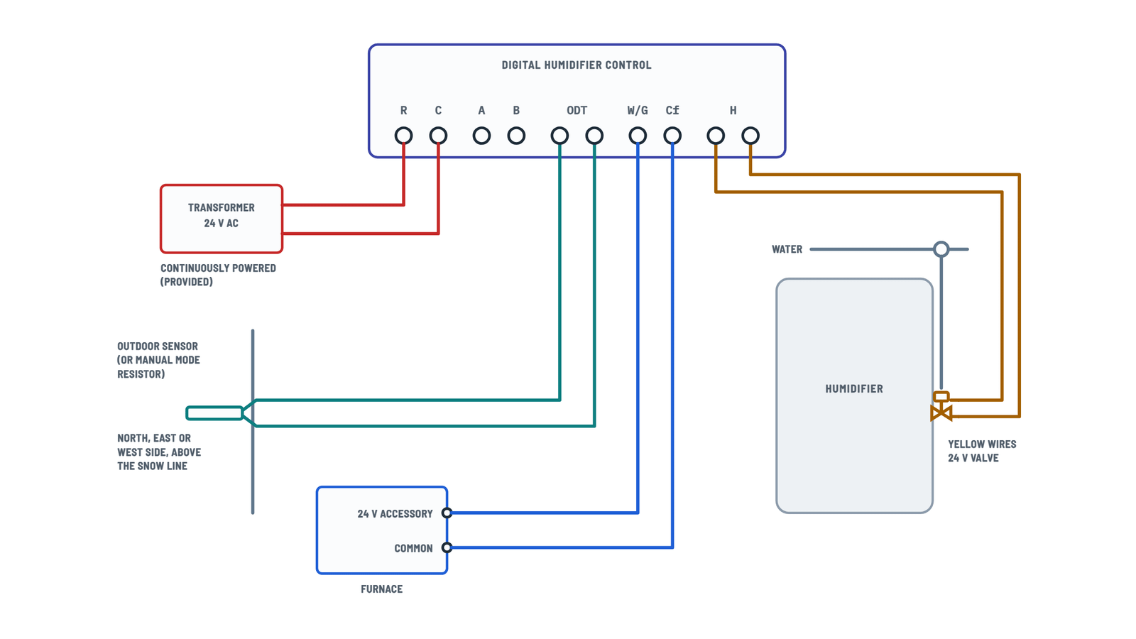
Aprilaire 600 Humidifier Wiring Diagram
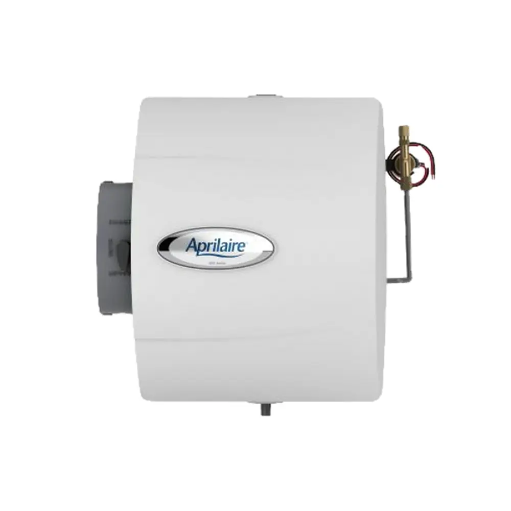
Aprilaire 600 wiring
Choose the control type; tap any terminal or component to see how it connects.
Terminals and components · 5
- 24 V AC
- Control
- Outdoor sensor
- Furnace signal
- Humidifier
- Model 50
Terminals
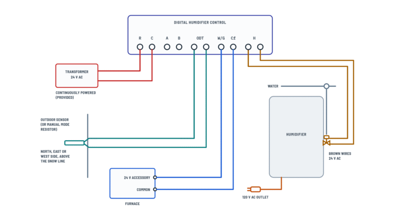
Terminal Goes to R · C Humidifier 24 V transformer ODT Outdoor sensor (or manual mode resistor) W/G · Cf Furnace 24 V accessory terminal and common H · H The yellow valve wires Other options
The control instructions include other wiring options.
Caution
Do not wire the transformer primary into the furnace blower circuit.
Location
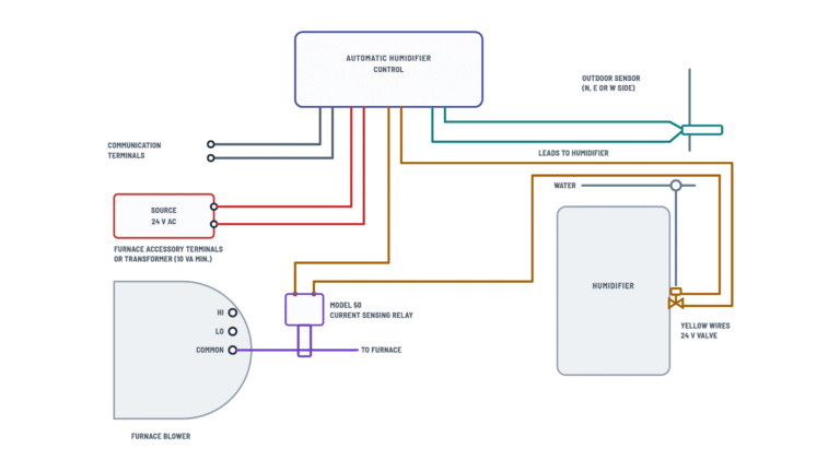
On the north, east or west side of the home, above the expected snow line.
Manual mode
Without an outdoor sensor, install the manual mode resistor on ODT.
Furnace terminals
They may be labeled “HUM”, “ACC” or “EAC”. Check the furnace manufacturer for voltage and operation.
Caution
If the accessory terminal is 120 V, install a 24 V transformer.
How to connect it
Connect each H terminal to one of the two yellow valve wires.
Caution
Do not use an external 24 V or 120 V source on these wires: it can damage the humidifier.
Setting
The dial shows the recommended humidity for the outdoor temperature.
Caution
Power the transformer from a 120 V AC circuit other than the blower motor circuit; it can be fed from the hot 120 V line before it enters the furnace.
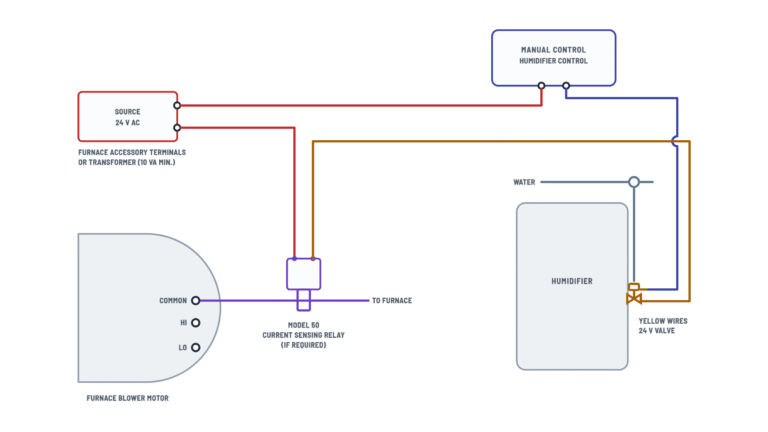
Without Model 50
Some furnaces have accessory terminals that are powered only while the blower runs; then the Model 50 may not be needed. Check with the furnace manufacturer.
How to connect it
Connect one of the yellow valve wires to the second control terminal and the other to the Model 50 (or straight to the source if not used).
Caution
Do not use an external 24 V or 120 V source on these wires: it can damage the humidifier.
How to connect it
- Run the blower motor common wire through the Model 50 sensor.
- Connect its two leads in the 24 V loop, between the source and the humidifier.
Caution
Install it only in the 24 V humidifier control circuit, never in the transformer primary circuit.
About This Diagram
This diagram is redrawn from page 1 of the Aprilaire 600 Humidifier manual, and we offer it completely free and in English. We have also categorized it in the Humidifiers (HVAC & Water Heating) section on Diagramverse, and it has been rated by 1 user with an average rating of 5.0. If you have any specific questions about the Aprilaire 600 Humidifier Wiring Diagram, we suggest checking the Frequently Asked Questions (FAQs) section.
Printable Aprilaire 600 Wiring Diagrams


Wiring Instructions
Before you start
First, figure out which variant you have. On the Aprilaire 600 · Digital tab, the Digital humidifier control has terminals R, C, A, B, ODT, Cf, W/G and H. It comes with its own 24 V transformer and an outdoor temperature sensor. On the 600M · Manual tab, the Manual humidifier control has two terminals wired in series with the solenoid valve. It runs from a separate 24 V source and often uses a Model 50 current sensing relay. If your control has a digital readout and a Test/Reset position on the knob, you have a 600.
The humidifier is meant to be installed by a qualified heating and air conditioning contractor, following all local, state and federal codes. If it isn't, the warranty is void. Running a new 120 V feed to the transformer may require a licensed electrician or a permit where you live, so check before you start.
Tools and materials:
- A multimeter that reads AC volts
- A wire stripper and screwdrivers
- A drill with a 3/4" bit for the digital control's sensor
- Low voltage wire, which is not supplied
No wire gauge is specified. For short 24 V runs, general good practice is 18 AWG multi-conductor thermostat cable. For the 600M you also need a 24 V AC source: either the furnace accessory terminals or a transformer rated 10 VA minimum. You may also need a Model 50.
Turn the humidifier control to OFF or its lowest setting. Turn off power to the furnace and confirm with your meter that it is dead before you open any panel.
Step-by-step wiring
- Finish mounting the humidifier, the water line and the drain hose before you do any wiring. Leave the saddle valve closed until you test.
- Mount the control. The Digital humidifier control goes on the return duct at least 6" upstream of the bypass duct connection or the humidifier. Its RH sensor goes through a 3/4" hole with the gasket around the sensor cage. The Manual humidifier control can go in the return duct (the same 6" rule applies) or on an interior wall away from drafts and heat sources.
- 600 only: mount the Outdoor temperature sensor on the north, east or west side of the home, above the expected snow line. Run two wires to the ODT terminals. Polarity does not matter.
- 600 only: install the supplied 24 V transformer on a 120 VAC source other than the furnace motor circuit. You can take it from the hot 120 VAC line before it enters the furnace. Never wire it into the blower circuit. Connect its 24 V secondary to R and C, and leave A and B empty.
- 600 only: wire the Furnace signal. Connect W/G to the 24 V accessory terminal on the furnace control board, which may be labeled HUM, ACC or EAC. Connect Cf to furnace common. Check with the furnace manufacturer that the terminal outputs 24 VAC and find out when it energizes. If it is a 120 V terminal, install a 24 V transformer rather than connecting it directly.
- 600 only: connect the two H terminals to the two yellow wires of the Solenoid valve. Polarity does not matter.
- 600M only: run one wire from the 24 V source to Terminal 1 of the Manual humidifier control. Run Terminal 2 to one yellow wire of the 24 V solenoid valve. Return the other yellow wire to the other side of the 24 V source, through the Model 50 contact if you use one.
- 600M with Model 50: route the blower motor common wire through the sensor of the Current sensing relay. Wire the relay's contact into the 24 VAC humidifier loop only, never into a transformer primary.
- Give each connection a gentle tug. Secure the low voltage wire away from hot surfaces, sharp plenum edges and the blower. Then close all panels.
Testing and start-up
Restore power to the furnace and the transformer. On a 600, the control's display should light right away, because R and C are powered all the time. Measure about 24 VAC between R and C, which may read a little higher with no load. Then start a call for heat and measure about 24 VAC between W/G and Cf while the furnace runs.
Open the saddle valve. With the furnace fan running, turn the knob past 7 to Test/Reset. You should hear the solenoid click, the green Humidifier On light should come on, and water should flow for one minute. Then set the dial to 5 as a starting point. Do not leave the knob on Test/Reset: after one minute the humidifier stops working. Confirm the internal mode switch is set to automatic, unless you deliberately want manual mode, which shows an M in the display.
On a 600M, open the saddle valve, turn the control to its highest setting and turn on the furnace. Let it run until water flows out of the drain, then return the knob to the proper setting. If you installed a Model 50, check that the valve stays off whenever the blower is off.
Before you leave, make sure:
- the saddle valve is fully open
- every plumbing joint is watertight
- the bypass damper is on WINTER for the heating season
Safety notes
- The control and the solenoid valve are 24 VAC devices rated 24 VAC, 60 Hz, 0.5 A. Never connect them to 120 V AC.
- The transformer primary and the furnace carry 120 V, which can cause serious injury from electric shock. Keep power off until every connection is complete.
- On a downflow furnace, make sure the blower keeps running after a heat call ends. Otherwise heat can damage a control mounted in the duct.
- Water over 125°F can scald instantly. Shut off the hot water supply before tapping a hot line.
- Plenum cutouts have sharp edges, so wear gloves.
- Do not install the humidifier where it can freeze.
Troubleshooting
| Symptom | Probable Cause | What to Check |
|---|---|---|
| The digital control's display is dark, even with the furnace on | No power on R and C, or the transformer is wired to a circuit that switches off | Measure between R and C. You should read about 24 VAC at all times. If the voltage drops when the blower stops, move the 24 V transformer to a separate, always-on 120 VAC source. |
| The display works, but the humidifier never runs during heating | The furnace signal is missing: W/G or Cf is disconnected, or W/G is on a terminal that never energizes | During a heat call, measure between W/G and Cf. You should read about 24 VAC. If not, move W/G to the HUM, ACC or EAC accessory terminal and Cf to furnace common. |
| The valve doesn't click when the knob is on Test/Reset | Loose wire at H, a wrong connection to the yellow wires, or the furnace fan is not running | Turn on the fan, set Test/Reset and measure across the two yellow wires within one minute. You should read about 24 VAC. If you have voltage but no click, the solenoid valve is faulty. |
| The solenoid burned out or the control died right after it was connected | The furnace accessory terminal is 120 V, not 24 V | Measure the accessory terminal against common. If you read 120 V, disconnect it and power the humidifier circuit from a 24 V transformer instead. |
| The transformer runs hot, hums or fails early | The transformer is wired into the furnace blower motor circuit | Trace the transformer primary. Move it to a 120 VAC source other than the blower circuit, for example the hot line before it enters the furnace. |
| 600M: water runs through the panel while the blower is off | The Model 50 is missing, or its sensor is on the wrong wire | Make sure the blower motor common wire passes through the Model 50 sensor and its contact is in series with the 24 V loop. With the blower off, there should be 0 VAC across the yellow wires. |
| 600M: the humidifier never runs, even at the highest setting | The Model 50 contact is wired in the transformer primary, the 24 V source is undersized, or there is a loose wire at Terminal 1 or 2 | Wire the Model 50 contact in the 24 VAC loop only. Check that the transformer is rated at least 10 VA. Measure 24 VAC at the yellow wires with the blower running and the knob at maximum. |
| Windows fog or frost on cold days with the digital control | The outdoor sensor is disconnected or badly placed, or the control is set to manual mode | Check both ODT wires. Mount the sensor on the north, east or west side, out of the sun and above the snow line. If the display shows M, set the internal switch back to automatic. |
| The red Service Required light flashes and an error code shows | A fault the control has detected, often caused by a loose connection | Write down the code (E1, E2, E3 or E4). With power off, recheck every terminal: R, C, ODT, W/G, Cf and H. If the code comes back, contact AprilAire Technical Support. |
| The control acts erratically or fails on a downflow furnace | Heat builds up in the duct after the heat call ends and the blower stops | Set the furnace so the blower keeps running after the heat call ends. Then confirm the control works normally again. |
| The valve clicks but no water reaches the panel or the drain | The saddle valve is closed, or the in-line strainer or orifice is blocked | Open the saddle valve fully. Shut off the water, then clean the strainer at the valve inlet and the orifice in the feed tube, or replace them. |