Aprilaire 500M Humidifier Wiring Diagram
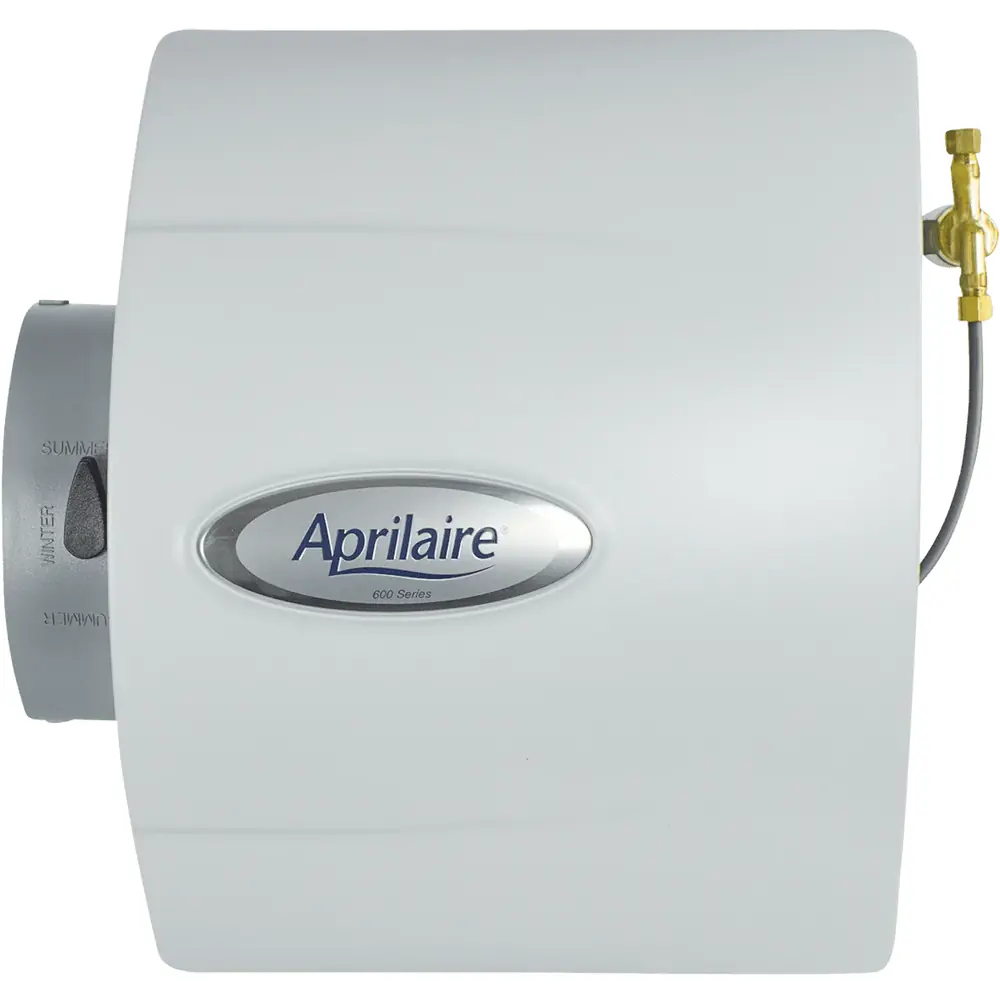
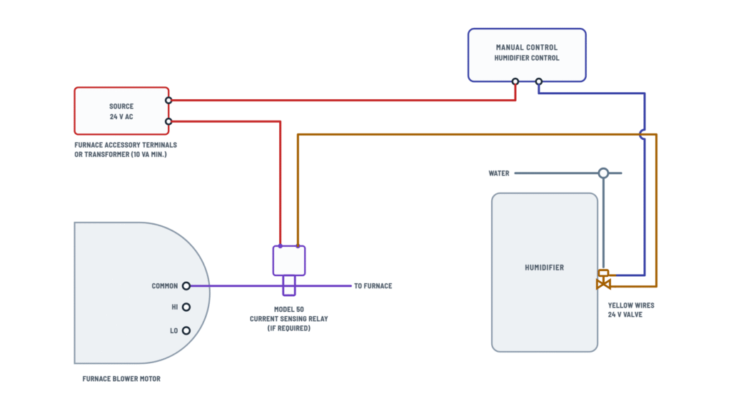
Aprilaire 500M wiring
Choose the control type; tap any terminal or component to see how it connects.
Terminals and components · 4
- 24 V AC
- Control
- Outdoor sensor
- Furnace signal
- Humidifier
- Model 50
Setting
The dial shows the recommended humidity for the outdoor temperature.
Caution
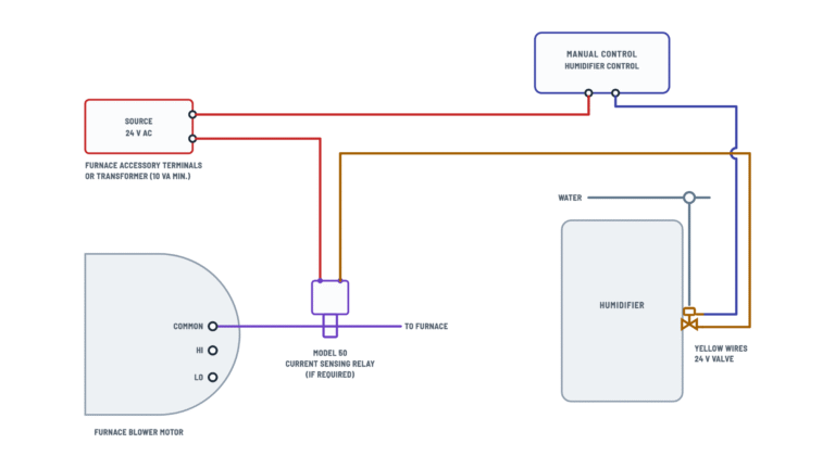
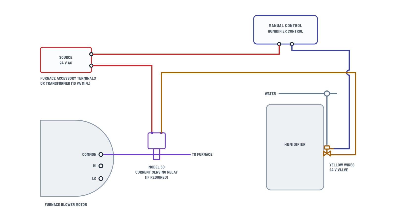
Power the transformer from a 120 V AC circuit other than the blower motor circuit; it can be fed from the hot 120 V line before it enters the furnace.
Without Model 50
Some furnaces have accessory terminals that are powered only while the blower runs; then the Model 50 may not be needed. Check with the furnace manufacturer.
How to connect it
Connect one of the yellow valve wires to the second control terminal and the other to the Model 50 (or straight to the source if not used).
Caution
Do not use an external 24 V or 120 V source on these wires: it can damage the humidifier.
How to connect it
- Run the blower motor common wire through the Model 50 sensor.
- Connect its two leads in the 24 V loop, between the source and the humidifier.
Caution
Install it only in the 24 V humidifier control circuit, never in the transformer primary circuit.
Terminals
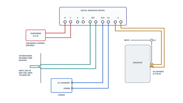
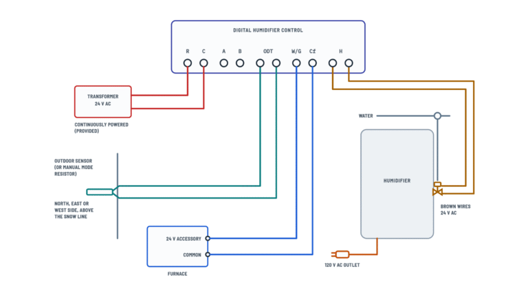
Terminal Goes to R · C Humidifier 24 V transformer ODT Outdoor sensor (or manual mode resistor) W/G · Cf Furnace 24 V accessory terminal and common H · H The yellow valve wires Other options
The control instructions include other wiring options.
Caution
Do not wire the transformer primary into the furnace blower circuit.
Location
On the north, east or west side of the home, above the expected snow line.
Manual mode
Without an outdoor sensor, install the manual mode resistor on ODT.
Furnace terminals
They may be labeled “HUM”, “ACC” or “EAC”. Check the furnace manufacturer for voltage and operation.
Caution
If the accessory terminal is 120 V, install a 24 V transformer.
How to connect it
Connect each H terminal to one of the two yellow valve wires.
Caution
Do not use an external 24 V or 120 V source on these wires: it can damage the humidifier.
About This Diagram
This diagram is redrawn from page 1 of the Aprilaire 500M Humidifier manual, and we offer it completely free and in English. We have also categorized it in the Humidifiers (HVAC & Water Heating) section on Diagramverse, and it has been rated by 1 user with an average rating of 5.0. If you have any specific questions about the Aprilaire 500M Humidifier Wiring Diagram, we suggest checking the Frequently Asked Questions (FAQs) section.
Printable Aprilaire 500M Wiring Diagrams

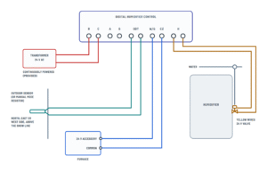
Wiring Instructions
Before you start
First, find the tab that matches your humidifier. Choose Aprilaire 500M · Manual if your unit came with a knob-type Manual humidifier control, which can mount on the return duct or on a wall. Choose 500A · Digital if it came with the Automatic Digital Humidifier Control and an outdoor temperature sensor. The current Model 500 is the same as the earlier 500A, so it also uses the Digital variant.
This humidifier should be installed by a qualified heating and air conditioning contractor, following all local, state and federal codes. The warranty is void if it is not. Have these ready:
- Low voltage wire, which is not supplied. The sources don't give a gauge. Common practice is 18 AWG thermostat cable, with two conductors for each run and a spare conductor where you can.
- A screwdriver, wire strippers, a multimeter that reads AC volts, and wire nuts.
- The supplied 24 VAC transformer and humidifier control. You also need a Model 50 current sensing relay if your furnace has no 24 V accessory terminal that turns on with the blower.
- The furnace manual. It tells you the voltage and how the accessory terminals behave. They may be labeled HUM, ACC or EAC.
Turn off power to the furnace at its service switch or breaker, and confirm with your meter that it is off. If you will add a 120 VAC feed for the transformer, that is line-voltage work. Many areas require a licensed electrician or a permit for it.
Step-by-step wiring
- Finish mounting the humidifier, bypass duct, water line and drain before you run any wire. Then turn the control knob to OFF.
- Pick a 24 V source. On the 500M, you can use the furnace's 24 VAC accessory terminals or a transformer rated at least 10 VA. On the 500A, the 24 V transformer must power the control all the time, so it can't come from a terminal that only turns on with a heat call.
- Power the transformer's 120 VAC primary from a circuit other than the furnace motor circuit. You may tap the hot 120 VAC line before it enters the furnace. Never connect the transformer to the blower motor wiring, because this can make components fail early.
- 500M: Run one wire from the 24 V source to Terminal 1 of the Manual humidifier control. Connect Terminal 2 to one of the yellow solenoid valve wires.
- 500M: Connect the other yellow wire back to the 24 V source. If you use a Model 50, wire its contact into this return path. Keep the Model 50 in the 24 VAC humidifier control circuit only, never in the transformer primary.
- 500M with Model 50: Pass the furnace blower motor common wire through the sensor on the Model 50. This makes the humidifier run only while the blower runs.
- 500A: Connect the transformer's 24 V secondary to R and C on the Digital control.
- 500A: Connect W/G to the furnace's 24 V accessory terminal and Cf to furnace common. If that terminal supplies 120 V instead of 24 V, add a 24 V transformer rather than connecting it directly.
- 500A: Mount the outdoor temperature sensor on the north, east or west side of the home, out of direct sun and above the expected snow line. Run two wires to the ODT terminals. Polarity doesn't matter.
- 500A: Connect the two H terminals to the yellow solenoid valve wires. Leave A and B empty for this wiring.
- Tighten every terminal screw and wire nut, tug each wire gently, and secure the cables away from hot surfaces and sharp duct edges.
Testing and start-up
Fully open the saddle valve and set the bypass damper handle to WINTER. Then turn the furnace power back on.
- 500M: Turn the control to its highest setting and start a heat call. When the blower starts, you should hear the solenoid click. Water should then fill the distribution tray and soon run steadily from the drain. While the valve is on, the yellow wires should read about 24 VAC. If they read near zero, nothing is reaching the valve.
- 500A: Check that R to C reads about 24 VAC even when the furnace is idle, and that W/G to Cf reads 24 VAC during a heat call. With the blower running, turn the knob to Test/Reset. The humidifier should run for one minute. Don't leave the knob there: move it back to the setting you want.
- Let the humidifier run until water drains. Check that all plumbing joints are watertight and all electrical connections are secure.
- Set the control to the recommended humidity for the current outdoor temperature.
Safety notes
- The humidifier, the controls and the Model 50 contact work at 24 VAC, and the valve is rated 24 VAC, 60 Hz, 0.5 A. Connecting 120 VAC to any of them will destroy the valve or the control. It is also a shock and fire hazard.
- The transformer primary and the furnace both carry 120 V. Turn off power and confirm it is off before touching anything inside the furnace cabinet.
- On a downflow furnace, set the blower to keep running after the heat call ends. Otherwise heat can damage the humidifier control.
- If you tap a hot water line, shut off the hot water supply first. Water above 125°F can scald instantly.
- Keep the humidifier and its water line where they cannot freeze.
Troubleshooting
| Symptom | Probable Cause | What to Check |
|---|---|---|
| Humidifier never turns on and the valve never clicks | No 24 V reaching the solenoid valve, from a dead transformer, a loose terminal or the wrong source | During a call for humidity with the blower running, measure across the yellow wires. You should see about 24 VAC. If not, check the transformer secondary, then Terminal 1 and 2 on the 500M or the H terminals on the 500A. |
| Digital control display is dark or only lights up while the furnace runs | R and C are powered from a heat-call terminal instead of a continuous 24 V source | Measure R to C with the furnace idle. It must read about 24 VAC. Move R and C to the supplied transformer, which stays powered all the time. |
| Digital control is on but never runs the humidifier during heating | W/G or Cf is not connected, or the accessory terminal is not 24 V | During a heat call, measure W/G to Cf. You should see 24 VAC. If the furnace terminal supplies 120 V, add a 24 V transformer. Check the furnace manual for when the terminal turns on. |
| Water runs to the drain even when the blower is off | The valve is powered without a blower interlock: the Model 50 contact is bypassed, or the 24 V source stays on | Make sure the Model 50 contact is wired in series in the 24 V loop. Also make sure the accessory terminal you used only turns on with the blower. |
| With the Model 50 installed, the humidifier never runs | The Model 50 sensor is on the wrong wire, or the relay is in the transformer primary | Pass the blower motor common wire through the sensor, not a speed lead or a 24 V wire. Move the Model 50 contact into the 24 VAC control circuit. |
| Transformer hums, runs hot or fails after a short time | The transformer primary is connected to the blower motor wiring | Rewire the 120 VAC primary to a separate source, or to the hot line before it enters the furnace, never the blower circuit. Replace the transformer if it is damaged. |
| Furnace low-voltage fuse blows or the control board resets when the humidifier turns on | A short in the valve wiring, or the accessory output can't supply enough power | With power off, look for pinched or bare yellow wires. Check that the 24 V source is rated at least 10 VA, or use the separate supplied transformer. |
| Humidifier runs constantly and won't shut off when the knob is turned to OFF | The control is bypassed, with the two control wires or the H terminals joined together | Turn the knob to OFF and measure across the yellow wires. You should see 0 V. If 24 V is still there, look for wires tied together that skip the control. |
| Digital control won't lower humidity in cold weather, or shows the red Service Required light after you install it | The outdoor sensor is not connected, has a broken wire or is in a bad location | Check both ODT wires for a broken or loose connection. Move the sensor to a shaded north, east or west wall above the snow line. Note any error code and contact support if it stays on. |
| Valve clicks but no water reaches the humidifier | The saddle valve is closed, or the strainer or orifice is clogged | Open the saddle valve fully. With power and water off, clean the inline strainer and check that the small opening in the orifice is clear. |