Dometic Duo Therm RV Thermostat Wiring Diagram
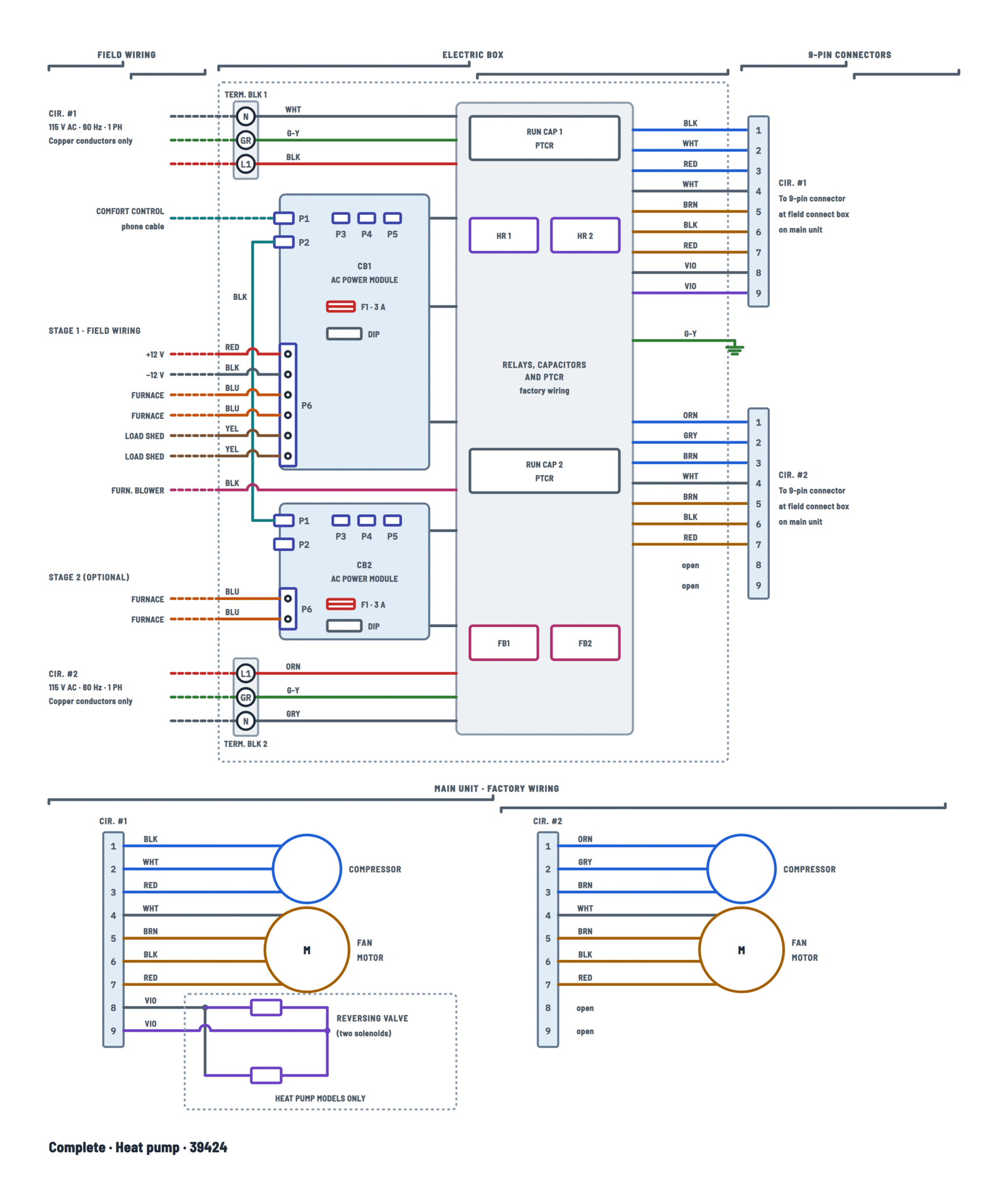
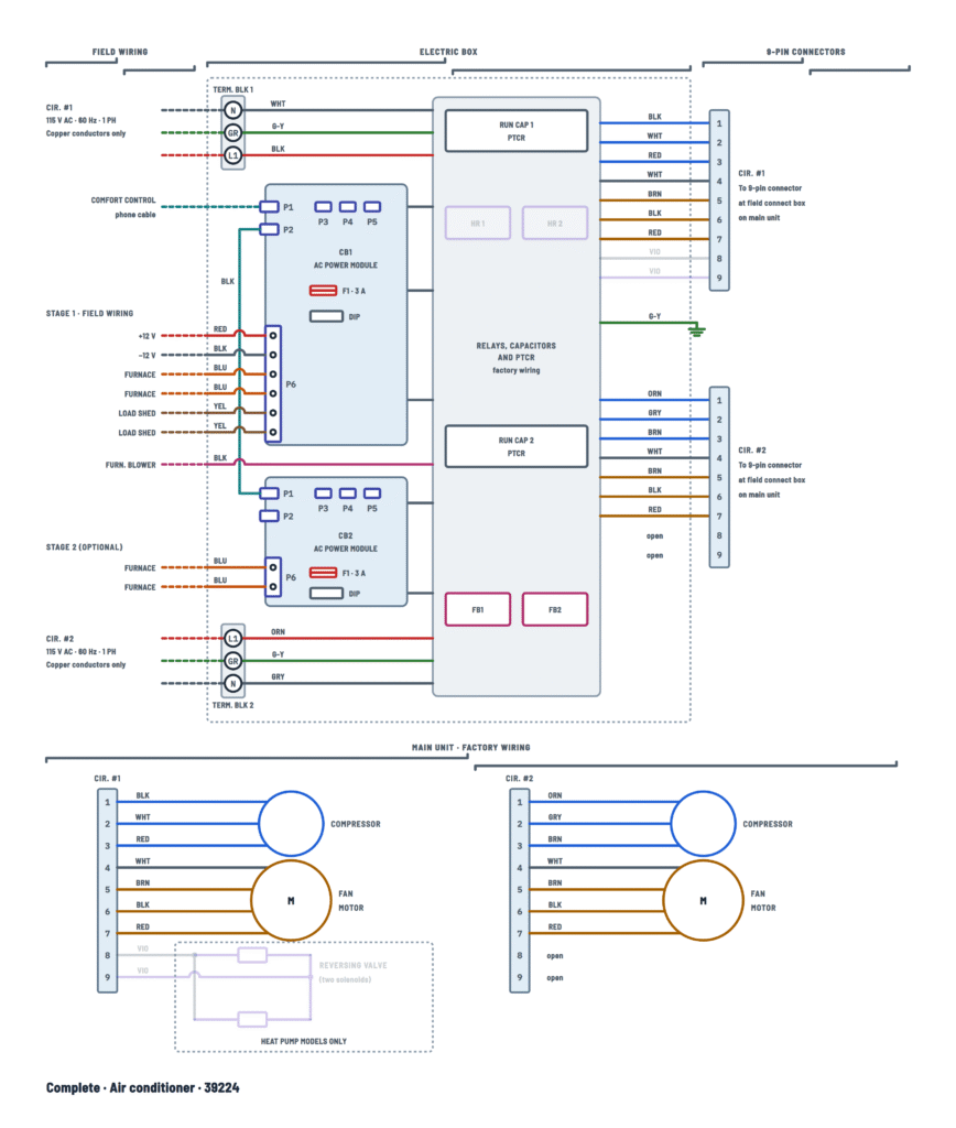
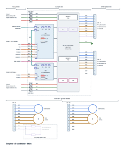
Typical dual basement wiring
Electric box with the two 115 V circuits, the Comfort Control Center field wiring and the 9-pin connectors to the unit.
Terminals and components · 18
- Line and +12 V
- Neutral and common
- Ground
- Communication
- Furnace
- Compressor
- Fan motor
- Reversing valve
- Field wiring
Terminals
Terminal Wire Function L1 BLK Line GR G-Y Ground N WHT Neutral Connection
Dual units (39224 and 39424) take two 115 V AC circuits. Circuit 1 goes to terminal block CIR 1 and circuit 2 to terminal block CIR 2: don't swap them. Use copper conductors only and check for 115 V AC at each terminal block.
Circuit protection
Model Protection 39224 15 A T.D. fuse or 15 A HACR breaker 39424 15 A T.D. fuse or 15 A HACR breaker Warning
- Shock hazard: disconnect the power supply to the unit (both 115 V AC circuits) before working on it.
Terminals
Terminal Wire Function L1 ORN Line GR G-Y Ground N GRY Neutral Connection
Run a separate circuit, with its own protection, from the breaker box to terminal block CIR 2. Use copper conductors only.
Circuit protection
Model Protection 39224 15 A T.D. fuse or 15 A HACR breaker 39424 15 A T.D. fuse or 15 A HACR breaker Warning
- Shock hazard: disconnect the power supply to the unit (both 115 V AC circuits) before working on it.
Connection
The Comfort Control Center communications phone cable enters the electric box and plugs into the circuit 1 power module (CB1). The other CB1 jack carries the link to jack P1 on CB2.
Check
The figure doesn't mark which of the two CB1 jacks (P1 or P2) takes the Comfort Control Center cable: use the one the link to CB2 leaves free.
Caution
- Improper connections can cause component damage.
Connection
Run the two 12 V DC wires from the RV to the circuit 1 power module: red to 12V+ and black to 12V−. Only this board takes the 12 V DC.
If there's no voltage
Check the RV's 12 V DC fuse or breaker and fuse F1 on the board.
Caution
- Improper connections can cause component damage.
Connection
Connect the two thermostat wires from the gas furnace to the stage 1 FURNACE terminals. The Comfort Control Center turns the furnace on through them.
Caution
- Improper connections can cause component damage.
Function
Lets an RV energy management system ask the unit to stop drawing power.
Check
The manual doesn't explain how this input is used: connect it only if the RV has an energy management system made for it.
Function
Two of the box's four relays (FB, furnace blower) run this circuit. The field wire goes to the furnace blower motor, if used.
Relay check (T91, 120 V)
Coil COM–NC COM–NO Not energized Continuity Open Energized Open Continuity Check
The figure doesn't show the connection at the furnace: follow the furnace instructions.
Warning
- Shock hazard: disconnect the power supply to the unit (both 115 V AC circuits) before working on it.
Use
In typical installations the furnace wires go to stage 1 (CB1); these CB2 terminals are optional.
Check
Use them only if your installation instructions call for it.
Configuration
Item Setting DIP All OFF P3 Ambient sensor (red) P4 Remote sensor, if used (white) Before changing
Turn the Comfort Control Center off before changing the configuration. A wrong configuration makes the unit run erratically or not at all.
Caution
- Improper connections can cause component damage.
Configuration
Item Setting DIP All OFF P4 Remote sensor, if used (white) Before changing
Turn the Comfort Control Center off before changing the configuration. A wrong configuration makes the unit run erratically or not at all.
Caution
- Improper connections can cause component damage.
Configuration
Item Setting STAGE (2) ON Other DIPs OFF P3 Ambient sensor (red) Operation
Circuit 2 is staged, with a delay from circuit 1. Before diagnosing, make sure circuit 2 should be operating.
Caution
- Improper connections can cause component damage.
Configuration
Item Setting STAGE (2) ON Other DIPs OFF Operation
Circuit 2 is staged, with a delay from circuit 1. Before diagnosing, make sure circuit 2 should be operating.
Caution
- Improper connections can cause component damage.
Purpose
Protects the system from shorts or overloads caused by disconnecting or reconnecting components with the 12 V DC on.
Check
- Remove the fuse and check continuity: no continuity means replace it.
- Without removing it: measure with a DC voltmeter between ground or negative (−) and each side of the fuse. Voltage on both sides = good; on one side only = blown.
Pins
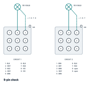
Pin Color Function 1 BLK Compressor (C) 2 WHT Compressor run (R) 3 RED Compressor start (S) 4 WHT 115 V common (motor) 5 BRN Motor capacitor 6 BLK High fan 7 RED Low fan 8 VIO 115 V common (valve) 9 VIO Reversing valve Check
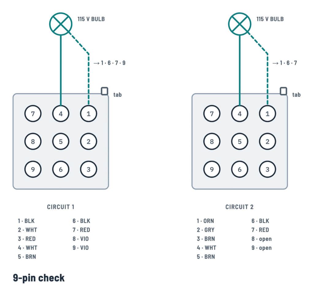
To check whether the board completes each circuit, disconnect the two 9-pin connectors and test with a 115 V incandescent bulb from pin 4 (WHT, 115 V common) to the other pins: if the circuit is completed, the bulb lights. If it lights and the component doesn't run, the fault is in the wiring to the component or in the component. Don't test pins 2, 3 and 5.
Note
- Don't use a voltmeter for these checks: it gives erroneous readings. Use a 115 V incandescent bulb.
Warning
- The bulb test is done with 115 V AC present: do it only if you are a qualified technician, and don't touch the terminals.
Pins
Pin Color Function 1 BLK Compressor (C) 2 WHT Compressor run (R) 3 RED Compressor start (S) 4 WHT 115 V common (motor) 5 BRN Motor capacitor 6 BLK High fan 7 RED Low fan 8 · 9 VIO Reversing valve (heat pump only) Check
To check whether the board completes each circuit, disconnect the two 9-pin connectors and test with a 115 V incandescent bulb from pin 4 (WHT, 115 V common) to the other pins: if the circuit is completed, the bulb lights. If it lights and the component doesn't run, the fault is in the wiring to the component or in the component. Don't test pins 2, 3 and 5.
Note
- Don't use a voltmeter for these checks: it gives erroneous readings. Use a 115 V incandescent bulb.
Warning
- The bulb test is done with 115 V AC present: do it only if you are a qualified technician, and don't touch the terminals.
Pins
Pin Color Function 1 ORN Compressor (C) 2 GRY Compressor run (R) 3 BRN Compressor start (S) 4 WHT 115 V common (motor) 5 BRN Motor capacitor 6 BLK High fan 7 RED Low fan 8 · 9 — Open Check
To check whether the board completes each circuit, disconnect the two 9-pin connectors and test with a 115 V incandescent bulb from pin 4 (WHT, 115 V common) to the other pins: if the circuit is completed, the bulb lights. If it lights and the component doesn't run, the fault is in the wiring to the component or in the component. Don't test pins 2, 3 and 5.
Before testing
Circuit 2 is staged and delayed: make sure it should be operating before diagnosing.
Note
- Don't use a voltmeter for these checks: it gives erroneous readings. Use a 115 V incandescent bulb.
Warning
- The bulb test is done with 115 V AC present: do it only if you are a qualified technician, and don't touch the terminals.
Terminals
Pin Wire Terminal 1 BLK C · common (compressor circuit) 2 WHT R · run 3 RED S · start Check
With the 115 V bulb only pin 1 (compressor circuit) is tested. Pins 2 and 3 are not tested.
Warning
- Shock hazard: disconnect the power supply to the unit (both 115 V AC circuits) before working on it.
Leads
Pin Wire Function 4 WHT 115 V common 5 BRN Motor capacitor (don't test) 6 BLK High fan 7 RED Low fan Warning
- Shock hazard: disconnect the power supply to the unit (both 115 V AC circuits) before working on it.
Operation
Pin 9 is energized in heat pump mode only. Two of the box relays (HR, heat relay) run this circuit.
Relay check (T91, 120 V)
Coil COM–NC COM–NO Not energized Continuity Open Energized Open Continuity Check
With the 115 V bulb between pin 4 and pin 9, the bulb should light in heat pump mode only.
Warning
- Shock hazard: disconnect the power supply to the unit (both 115 V AC circuits) before working on it.
Terminals
Pin Wire Terminal 1 ORN C · common (compressor circuit) 2 GRY R · run 3 BRN S · start Check
With the 115 V bulb only pin 1 (compressor circuit) is tested. Pins 2 and 3 are not tested.
Warning
- Shock hazard: disconnect the power supply to the unit (both 115 V AC circuits) before working on it.
Leads
Pin Wire Function 4 WHT 115 V common 5 BRN Motor capacitor (don't test) 6 BLK High fan 7 RED Low fan Warning
- Shock hazard: disconnect the power supply to the unit (both 115 V AC circuits) before working on it.
9-pin connector check
Face of both connectors with each pin's color and the 115 V bulb check.
Terminals and components · 11
- Common
- Compressor
- Fan
- Reversing valve
- Do not test
How to test
Disconnect the two 9-pin connectors that join the electric kit to the unit. Put one bulb lead on pin 4 (WHT, 115 V common) and the other on the pin under test: if the board completes the circuit, the bulb lights.
Result
If the bulb lights and the component doesn't run, the fault is in the wiring to the component or in the component itself.
Note
- Don't use a voltmeter for these checks: it gives erroneous readings. Use a 115 V incandescent bulb.
Warning
- The bulb test is done with 115 V AC present: do it only if you are a qualified technician, and don't touch the terminals.
Use
Pin 4 is the bulb reference point for all the checks.
How to test
Disconnect the two 9-pin connectors that join the electric kit to the unit. Put one bulb lead on pin 4 (WHT, 115 V common) and the other on the pin under test: if the board completes the circuit, the bulb lights.
Result
If the bulb lights and the component doesn't run, the fault is in the wiring to the component or in the component itself.
How to test
Disconnect the two 9-pin connectors that join the electric kit to the unit. Put one bulb lead on pin 4 (WHT, 115 V common) and the other on the pin under test: if the board completes the circuit, the bulb lights.
Result
If the bulb lights and the component doesn't run, the fault is in the wiring to the component or in the component itself.
How to test
Disconnect the two 9-pin connectors that join the electric kit to the unit. Put one bulb lead on pin 4 (WHT, 115 V common) and the other on the pin under test: if the board completes the circuit, the bulb lights.
Check
Air conditioner-only units (39224) have no reversing valve.
Do not test
These pins are the compressor run and start and the motor capacitor: don't test them with the bulb.
How to test
Disconnect the two 9-pin connectors that join the electric kit to the unit. Put one bulb lead on pin 4 (WHT, 115 V common) and the other on the pin under test: if the board completes the circuit, the bulb lights.
How to test
Disconnect the two 9-pin connectors that join the electric kit to the unit. Put one bulb lead on pin 4 (WHT, 115 V common) and the other on the pin under test: if the board completes the circuit, the bulb lights.
Result
If the bulb lights and the component doesn't run, the fault is in the wiring to the component or in the component itself.
Before testing
Circuit 2 is staged and delayed from circuit 1: make sure it should be operating.
How to test
Disconnect the two 9-pin connectors that join the electric kit to the unit. Put one bulb lead on pin 4 (WHT, 115 V common) and the other on the pin under test: if the board completes the circuit, the bulb lights.
Result
If the bulb lights and the component doesn't run, the fault is in the wiring to the component or in the component itself.
Do not test
These pins are the compressor run and start and the motor capacitor: don't test them with the bulb.
Use
There's nothing to test on these pins.
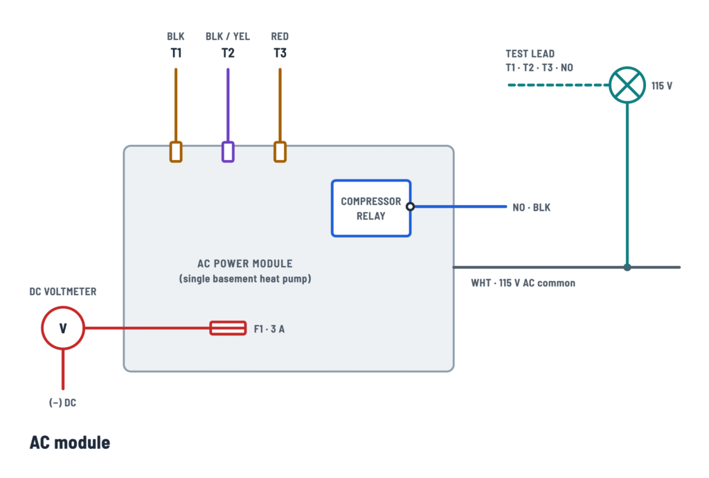
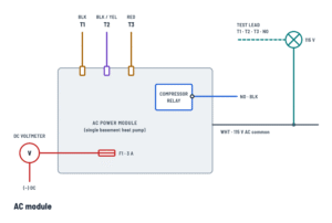
AC power module check (single basement heat pump)
Board output terminals tested with a 115 V bulb, and the 3 A fuse.
Terminals and components · 7
- Common
- Fan
- Reversing valve
- Compressor
- Test bulb
- Fuse
How to test
Remove the electric box cover and locate the AC power module. Put one bulb lead on the incoming 115 V AC WHT (common) and the other on each terminal: if the board completes the circuit, the bulb lights. If it lights and the component doesn't run, the fault is in the wiring to the component or in the component.
Note
- Don't use a voltmeter for these checks: it gives erroneous readings. Use a 115 V incandescent bulb.
Warning
- The bulb test is done with 115 V AC present: do it only if you are a qualified technician, and don't touch the terminals.
Check
The bulb between WHT and T1 lights when the board calls for high fan.
Check
The bulb between WHT and T2 lights in cooling mode and stays off in heat pump mode.
Check
The T2 wire color differs between the figure (yellow) and the text (black): identify it by terminal T2, not by color.
Check
The bulb between WHT and T3 lights when the board calls for low fan.
Check
The bulb between WHT and NO lights when the board calls for the compressor.
Warning
- The bulb test is done with 115 V AC present: do it only if you are a qualified technician, and don't touch the terminals.
Check
- Remove the fuse and check continuity: no continuity means replace it.
- Without removing it: DC voltmeter between ground or negative (−) and each side of the fuse. Voltage on both sides = good; on one side only = blown.
About This Diagram
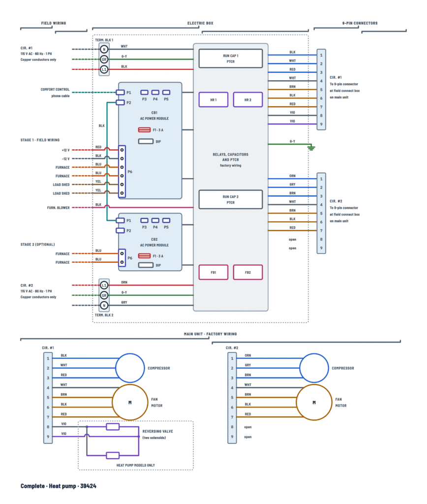
These diagrams are redrawn from pages 52–54 of the Duo Therm RV Thermostat User Manual, and we offer them completely free and in English. We have also categorized it in the Thermostats (HVAC & Water Heating) section on Diagramverse, and it has been rated by 1 user with an average rating of 5.0. If you have any specific questions about the Dometic Duo Therm RV Thermostat Wiring Diagram, we suggest checking the Frequently Asked Questions (FAQs) section.
Printable Dometic Duo Therm RV Wiring Diagrams
Wiring Instructions
Before you start
This diagram covers the Duo-Therm Comfort Control Center on a dual basement system: one electric box with two AC power module boards, CB1 and CB2, each running its own compressor and fan. Pick the variant that matches the model number on the rating plate. 39424 is the dual basement heat pump and 39224 is the dual basement air conditioner. The 9-pin check tab is for testing the two 9-pin connectors on these dual units. The AC module tab is for a single basement heat pump, which has only one board, so use it only if you have a single-compressor unit.
- Tools: insulated screwdrivers, wire stripper, RJ-11 crimping tool, a voltmeter that reads AC and DC, an ohmmeter, a clamp-on ammeter and a 115 V incandescent test bulb with leads.
- Power wiring: each unit needs two separate 115 V AC, 60 Hz circuits, CIR 1 and CIR 2. Protect each one with its own 15 A time-delay fuse or 15 A HACR breaker. Use copper conductors only. 12 AWG copper with ground is the usual run for these units. Confirm the size against the circuit length and your local code.
- 12 V DC wiring: run a dedicated 18–22 AWG line from the RV converter or battery. The control works between 10 and 30 V DC.
- Communication cable: flat 4-conductor, 26 gauge stranded copper (yellow, green, red, black) with a 4-position RJ-11 plug. Do not use a pre-made telephone extension cord.
- Isolation: switch off both 115 V AC breakers, unplug shore power, stop the generator and disconnect the battery positive. Then confirm with your meter that no AC voltage is present.
- Professional help: this equipment must be serviced by qualified personnel, and some states require that person to be licensed. All wiring must comply with national, state and local codes. If you are not comfortable working on 115 V branch circuits, have an electrician run the two supply circuits.
Step-by-step wiring
- Mount the Comfort Control Center 54 inches above the floor on an inside partition. Keep it away from sunlight, lamps, outside doors, windows and supply registers. If you use a remote sensor, mount the sensor to these rules instead.
- Make up the phone cable. Cut both ends square, strip only the outer jacket, and insert the conductors so the black wire is on your left when you look at the top of the plug with the spring clip facing you. Crimp both ends the same way. Plug one end into the Comfort Control Center and the other into CB1. Leave the factory link from CB1 to CB2 in place.
- Run the circuit 1 supply to the CIR 1 terminal block: L1 BLK, N WHT and GR G-Y. Run the circuit 2 supply to CIR 2: L1 ORN, N GRY and GR G-Y. Keep the two circuits on their own breakers and never swap them.
- Connect the 12 V DC supply to connector P6 on CB1: 12V+ RED and 12V− BLK. Check the polarity before you energize.
- Connect the two BLU furnace thermostat wires from the gas furnace to P6 on CB1. If your furnace supports a second stage, land its two BLU wires on P6 of CB2.
- Optional: connect the two YEL load shed wires to P6 on CB1. The energy management system must supply a normally open relay contact that closes when it wants the compressor off.
- Optional: wire the furnace blower through relays FB1 and FB2. This circuit does not work with every furnace, so confirm the connection with the furnace manufacturer first.
- Set the DIP switches with the Comfort Control Center switched OFF. On CB1, set every DIP switch OFF. On CB2, set the STAGE DIP (#2) ON and all others OFF.
- Plug in the sensors. On the 39424 heat pump, plug an ambient sensor into P3 (red) on each board. If you use a remote sensor, plug it into P4 (white). Leave P5 (blue) empty, because the freeze control is not used on basement units.
- Join the two 9-pin connectors (CIR #1 and CIR #2) between the electric box and the main unit's field connect box. Make sure they are fully seated and every pin is tight.
Testing and start-up
- With the unit OFF, measure AC voltage at each terminal block, then measure again under load. Both readings must stay between 103 and 126.5 V AC. Correct the supply before you run the system if they don't.
- Measure the incoming DC between RED (+) and BLK (−). It should read 10 to 30 V and must never exceed 30 V.
- Check the F1 3 A fuse on each board with a DC voltmeter, from negative to each side of the fuse. You should see voltage on both sides.
- Switch the Comfort Control Center ON. The display should light and show only the modes your installation supports. Select COOL and lower the setpoint. The compressor should start after about 2 minutes. Circuit 2 starts after circuit 1, and only once the stage differential is reached.
- On a 39424, select HEAT PUMP and confirm the reversing valve switches. In heat mode, the line at the top of the inside coil should feel warm.
- Use a clamp-on ammeter on each black supply wire to record the current draw, which tells you whether a breaker is tripping too early.
Safety notes
- The box contains two separate 115 V circuits, so turning off one breaker does not make it safe. Open both and verify zero volts at CIR 1 and CIR 2.
- Run and start capacitors can hold a charge after the power is off. Discharge them before you touch their terminals.
- Connecting or disconnecting components with 12 V DC applied can blow F1. Remove the DC power first.
- Live tests with the test bulb are energized-circuit work. Only a qualified technician should do them.
- Bond every ground (G-Y) to the casing ground, and never use the neutral as a ground.
Troubleshooting
| Symptom | Probable Cause | What to Check |
|---|---|---|
| Display stays blank when I turn the control ON | No 12 V DC, reversed 12V+/12V− polarity, blown F1 fuse, or a bad phone cable | Measure DC between RED (+) and BLK (−) at P6. It should read 10 to 30 V. Check F1 with a DC voltmeter for voltage on both sides. Confirm the cable has black on the left at both plugs, then run the reset procedure. |
| Control lights up but the unit does nothing, or acts erratically | Store-bought extension cable with reversed polarity, or the phone cable plugged into CB2 instead of CB1 | Replace the cable with a hand-crimped 4-conductor 26 gauge cable made the same way at both ends. Plug the Comfort Control Center into CB1. |
| First compressor runs but the second never starts | STAGE DIP (#2) not ON on CB2, no power on CIR 2, or the stage differential not reached yet | Turn the control OFF and set STAGE DIP #2 ON on CB2 only. Check for 103 to 126.5 V AC at CIR 2. Wait for the delay and check the differential setpoint. |
| Both compressors try to start at once, or the boards behave strangely | STAGE DIP set ON on CB1 as well, or other DIP switches left ON | Set every DIP on CB1 OFF and only STAGE (#2) ON on CB2, with the control switched OFF. |
| Breaker trips when a compressor starts | Both compressors fed from one circuit, CIR 1 and CIR 2 swapped, low voltage, or the wrong breaker type | Confirm circuit 1 lands on CIR 1 and circuit 2 on CIR 2, each on its own 15 A time-delay fuse or HACR breaker. Measure voltage under load and clamp the black wire for current draw. |
| Compressor won't come on at all, no hum | Load shed contact closed, loose 9-pin connector, or the furnace mode selected | Disconnect the YEL load shed wires and retest. Check the 9-pin pins are tight. Bulb-test pin 4 to pin 1, which should light when the compressor is called. |
| Fan only runs on one speed | Loose wire at pin 6 or 7 of the 9-pin connector, or an open motor winding | Bulb-test pin 4 to pins 6 and 7. With the power off, check continuity from WHT (pin 4) to BLK and RED and check the motor isn't grounded to G-Y. |
| Heat pump blows cold air in heat mode | Reversing valve not powered, missing ambient sensor, or the air conditioner variant wired as a heat pump | On the 39424, bulb-test pin 4 to pin 9 in heat mode, which should light. Check the solenoid reads about 465 ohms ±10%. Confirm the ambient sensor is in P3 (red). |
| Heat pump shuts off or switches to the furnace in cold weather | Normal low-temperature lockout below 24°F, or a faulty ambient sensor | Unplug the red P3 plug and measure ohms. It should read about 7876 ohms at 70°F, ±10%. Replace the sensor if the reading is out of range. |
| Room temperature overshoots or the unit cycles constantly | Remote sensor not in P4, or the sensor or control mounted near a register, an outside wall or in the sun | Plug the remote sensor into P4 (white). Relocate it 54 inches high on an inside partition, away from supply air. |
| Furnace blower doesn't run with the compressor | The furnace doesn't support the FB1/FB2 blower circuit, or the field wire is loose | Check the furnace manufacturer's connection instructions. Verify the BLK field wire at FB1 and FB2. |