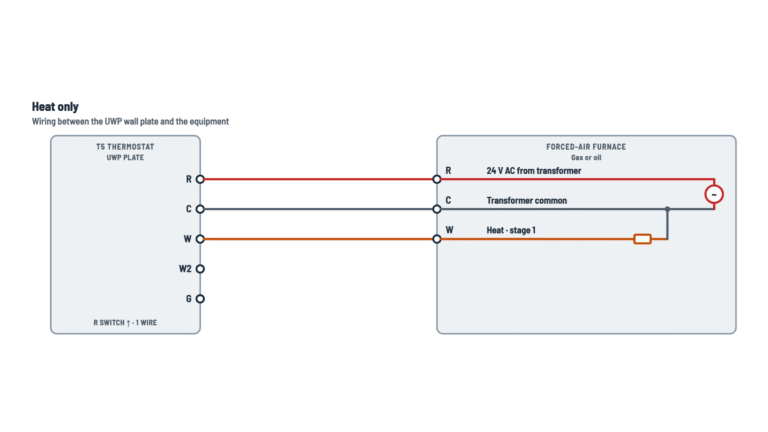
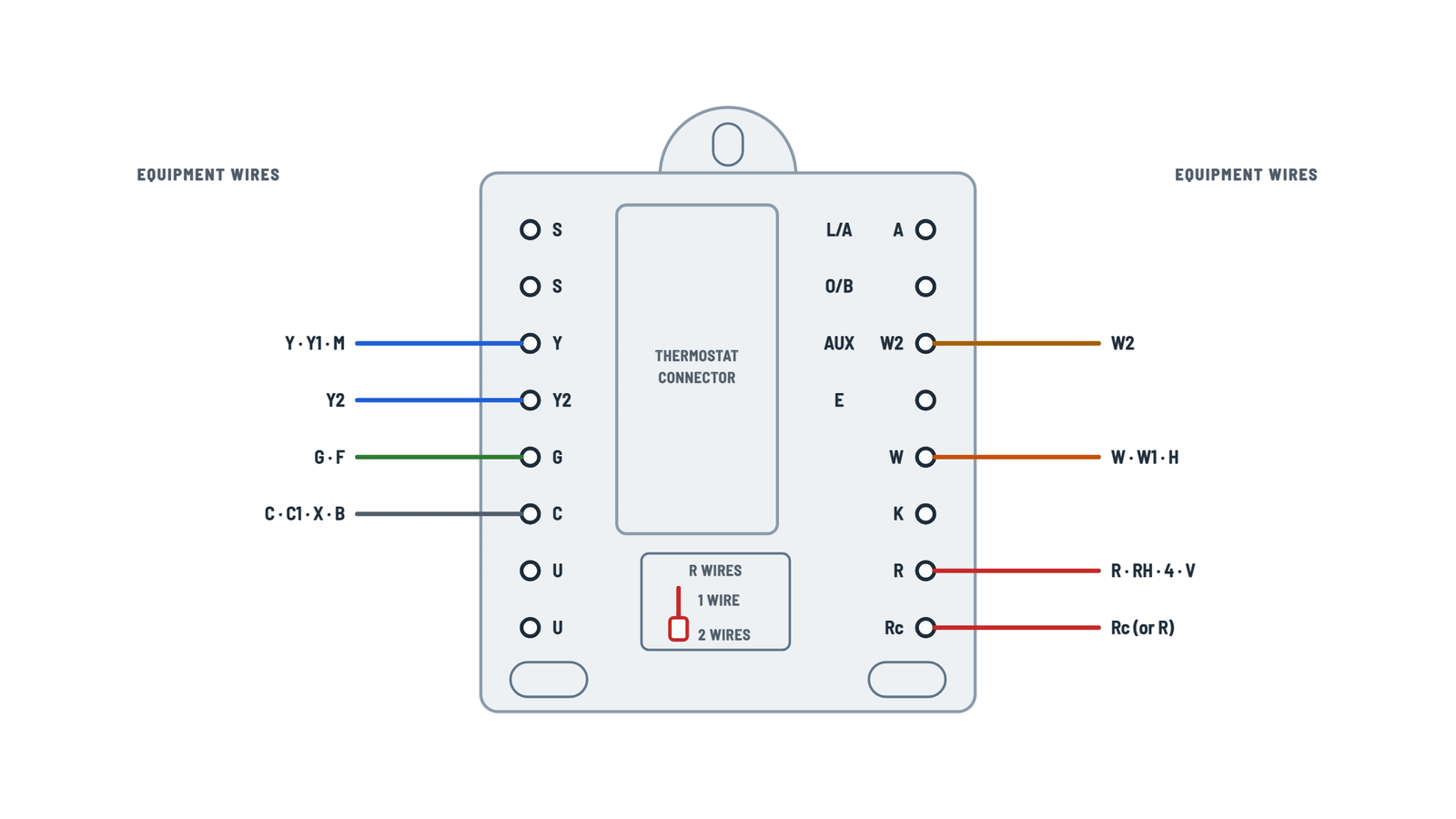
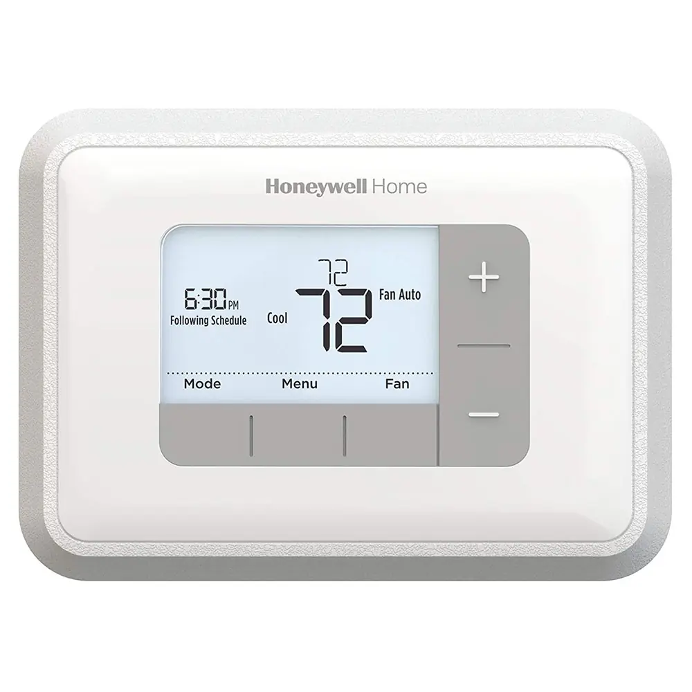
Honeywell RTH6360 Thermostat Wiring Diagram
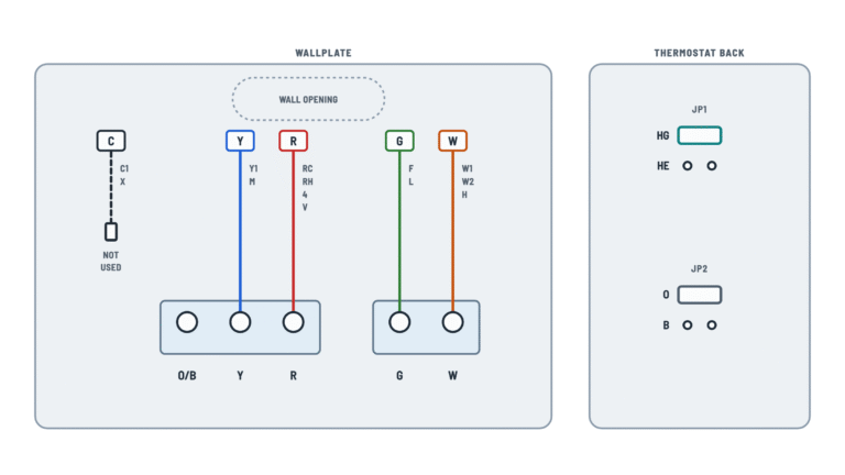
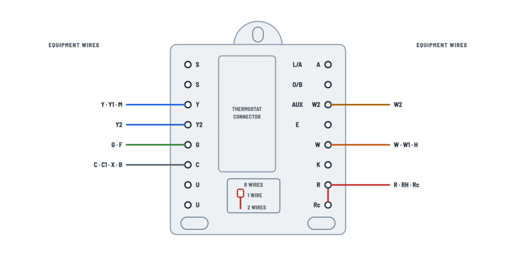
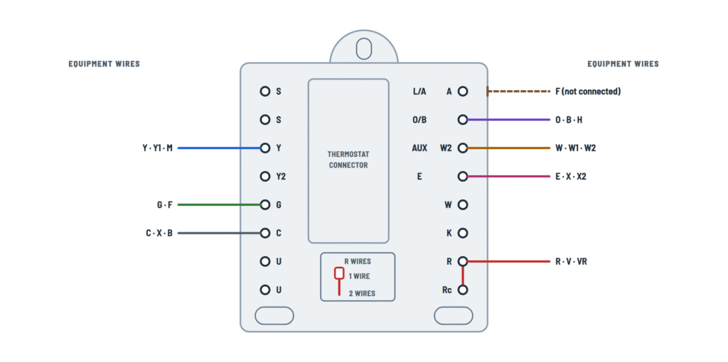
UWP wall plate
Plate terminals and the old thermostat's wire letters.
Terminals and components · 10
- R · Rc (24 V)
- Common
- Fan
- Cooling / compressor
- Heating
- Heating stage 2
- Reversing valve
- Aux heat
- Emergency heat
What it does
Brings 24 V from the heating transformer to the thermostat.
If you had R and RH
Connect the RH wire to the R terminal and the R wire to the Rc terminal. With R and Rc, each goes to its own terminal.
Jumpers
If the old thermostat had a jumper between R and Rc, remove it: the RTH6360 needs no jumpers.
What it does
Brings 24 V from the system's only transformer to the thermostat.
How to connect it
The single R wire (labeled R, RH or Rc) goes to the R terminal, with the R switch up.
Jumpers
If the old thermostat had a jumper, remove it: the RTH6360 needs no jumpers.
What it does
Brings 24 V from the heat pump's transformer to the thermostat.
R switch
Leave it up (1 wire).
Caution
If the old thermostat had both V and VR wires, stop: contact a qualified contractor.
What it does
Feeds the cooling outputs (Y, Y2) and the fan (G).
R switch
With two R wires, set the switch down (2 wires) so R and Rc stay separate.
When it goes down
When you connect two R wires: R (or RH) and Rc.
When it goes up
With a single R wire. The plate joins R and Rc internally, so no jumper is needed.
What it does
It is the transformer's common (0 V). It does not power the display: the thermostat always runs on two AA batteries.
If you had two C wires
With a single C or C1 wire, it goes to C. With two, tape each one separately and leave them unconnected.
What it does
It is the transformer's common (0 V). It does not power the display: the thermostat always runs on two AA batteries.
If you had two C wires
With a single C or C1 wire, it goes to C. With two, tape each one separately and leave them unconnected.
Separate B wire
If the old thermostat had separate O and B wires, the B wire goes to C. If C already has another wire, contact a contractor.
What it does
In Auto the fan runs only with heating or cooling; in On, all the time.
What it does
Starts the air conditioner compressor.
What it does
Starts the compressor; the O/B valve decides whether it cools or heats. Only one compressor stage is supported.
Protection
“Heat On” or “Cool On” may flash for up to 5 minutes: that is compressor protection.
Setup
Set function 220 to 2 cooling stages.
If you don't have it
Leave it empty: normal on single-stage systems.
Setup
Function 200 = 1 (forced air) or 3 (radiant); 205 selects the equipment type.
Setup
Set function 221 to 2 heating stages.
Shared terminal
W2 and AUX are the same terminal: on heat pumps it is used as AUX.
Setup
- 200 = 2 (heat pump)
- 218 = 0: valve energized in cooling (O)
- 218 = 1: valve energized in heating (B)
Separate O and B wires
O goes to O/B and B goes to C (if C is free).
What it does
Adds heat when the heat pump alone can't keep up.
Caution
Do not use W on heat pumps: aux heat goes to AUX or E. If you had Y1, W1 and W2, contact a contractor.
Setup
Function 221: 1 backup heat stage.
What it does
In Em Heat mode the thermostat uses only auxiliary heat, without the compressor.
What to do
Tape the wire and leave it unconnected. If you need the alert, a different thermostat model is required.
What it means
The plate is universal: it fits other thermostats. The RTH6360 does not support L/A, S or U.
Extra wires
If you had wires on terminals not shown here, the thermostat may not be compatible: contact a contractor.
About This Diagram
This diagram is redrawn from pages 12–13 of the Honeywell RTH6360 Thermostat manual, and we offer it completely free and in English. We have also categorized it in the Thermostats (HVAC & Water Heating) section on Diagramverse, and it has been rated by 1 user with an average rating of 5.0. If you have any specific questions about the Honeywell RTH6360 Thermostat Wiring Diagram, we suggest checking the Frequently Asked Questions (FAQs) section.
Printable Honeywell RTH6360 Wiring Diagrams
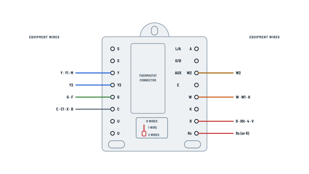
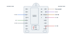
Wiring Instructions
Before you start
The Honeywell RTH6360 is a battery-powered thermostat for 24 V systems: gas, oil or electric forced air, hot water fan coils, boilers, steam and single-compressor air-to-air heat pumps. It does not work with 120/240 V line-voltage electric heat. If your old thermostat has thick black wires joined with wire nuts, or is marked 120 V or higher, stop. This thermostat will not work on that system.
You need a small flat-head screwdriver, a Phillips screwdriver, a pencil and a level. You may also need a wire stripper, needle-nose pliers and a drill with a 7/32 in bit. The box includes the UWP wall plate, screws, anchors and wire labels. Have two AA alkaline batteries ready. They always power the thermostat, even when a C wire is connected. Reuse the existing thermostat cable if you can. If you run new cable, use standard low-voltage thermostat wire (18 AWG is typical) and follow your equipment instructions and local code.
Call a licensed HVAC contractor if you find wires on terminals this thermostat does not support, a heat pump with both V and VR wires, or a heat pump with separate Y1, W1 and W2 wires.
Identify your diagram variant
- Conventional · one R wire: a furnace, boiler or air conditioner with a single R, RH or Rc wire. Set the R switch up.
- Conventional · R and Rc: separate heating and cooling transformers, so you have two R wires. Set the R switch down.
- Heat pump: the outdoor unit both heats and cools, usually with an O, B or O/B wire. Set the R switch up.
Step-by-step wiring
- Turn off power to the heating and cooling system at the breaker or at the equipment switch. To confirm it's off, set the old thermostat to call for heat or cooling. If nothing starts within 5 minutes, the power is off.
- Remove the old faceplate without disconnecting any wires. Take a clear photo that shows each wire and the letter of its terminal.
- Remove any jumpers between terminals, for example between R and Rc. The RTH6360 does not need them, and they don't count as wires.
- Write down which terminals have wires and their colors, and count the R-type wires: R, RH and Rc. Note any wire on L/A, S or U. The RTH6360 does not support these terminals, so a fault alert wire stays disconnected.
- Release each wire and label it with the letter of its old terminal, not its color. Wrap the wires around a pencil so they can't fall into the wall, then remove the old wall plate.
- Feed the wires through the back of the UWP, with at least 1/4 in of bare copper on each one. Level the plate, mark the holes, drill, and tap the anchors in until they are flush.
- Set the R switch: up for one R wire, down for two. With two wires, put Rc on the Rc terminal and R or RH on R. If your old thermostat had both R and RH, connect the R wire to Rc and the RH wire to R.
- Connect the remaining wires, one per terminal. Press each tab and push the wire into the inner hole: G to G, Y or Y1 to Y, W or W1 to W, C to C, plus Y2, W2, O/B, AUX and E if you have them. Tug each wire gently to check it holds.
- On a heat pump, the backup heat wire goes on AUX or E, never on W. If you had separate O and B wires, B goes on C. If C already has a wire, stop and call a contractor. On a conventional system with two C or C1 wires, tape each one separately and leave both disconnected.
- Check the wiring against your photo. Mount the UWP with all three supplied #8 1-1/2 in screws and close the door.
- Insert two AA alkaline batteries and snap the thermostat firmly onto the UWP.
Testing and start-up
Turn the power back on and set the date, clock format and time. Then work through System Setup: 200 for system type, 205 for equipment type, 218 for O or B on a heat pump, 220 for cooling or compressor stages, 221 for heat or backup heat stages, and 300 for manual or automatic changeover.
Test each function. In Heat, raise the setpoint above room temperature and the furnace, boiler or heat pump should start. In Cool, set it below room temperature and the compressor and fan should run. Set Fan to On to confirm the fan runs on its own. Heat On or Cool On may flash for up to 5 minutes while compressor protection is active. On a heat pump, confirm warm air in Heat and cool air in Cool, and test Em Heat if you have backup heat. If you have a meter, R to C at the wall plate should read about 24 V AC.
Safety notes
- The thermostat circuit is 24 V, but the furnace or air handler has 120/240 V inside. Keep the power off while wiring, and don't open equipment panels unless you are qualified.
- Keep bare wire ends apart. A short from R to C or to another terminal can blow the control board fuse or damage the transformer.
- If the old thermostat has a sealed mercury tube, don't put it in the trash. Take it to a hazardous waste or recycling site, and dispose of the RTH6360 the same way at the end of its life.
Troubleshooting
| Symptom | Probable Cause | What to Check |
|---|---|---|
| The screen is completely blank after installation | The batteries are missing, dead or in backwards. The C wire does not power this thermostat. | Install two fresh AA alkaline batteries in the back of the thermostat, the right way round, and snap it firmly back onto the UWP. |
| The screen works but nothing heats or cools | The system has no power, the furnace door switch is open, or the R wire is loose | Check the breaker and the equipment power switch, and make sure the furnace door is closed securely. Tug the R wire in its terminal. With a meter, R to C should read about 24 V AC. |
| Heat works but cooling does not, or the other way round | The R switch is in the wrong position for your number of R wires | With one R wire, the R switch must be up. With two R wires, it must be down, with Rc on the Rc terminal and R or RH on the R terminal. |
| The heat pump blows cold air in Heat and warm air in Cool | Reversing valve setting 218 doesn't match the O/B wire, or system type 200 is wrong | Set 200 to Heat Pump. If the valve energizes in cooling, set 218 to O; if it energizes in heating, set 218 to B. |
| I can't select Cool mode | Cooling stages are set to 0, or the system type is set to heat only | In System Setup, set 220 to 1 or 2 to match your equipment, and check that 200 matches your system. |
| The furnace heats but the blower never comes on | Equipment type 205 doesn't match the furnace, or the G wire is loose | Set 205 to your equipment, for example 4 for electric forced air. Check that the G wire is firmly seated in G, and test with Fan set to On. |
| Backup or emergency heat never comes on with the heat pump | The auxiliary heat wire is on W, or backup heat stages are set to 0 | Move the wire to AUX or E, never W. Set 221 to 1, then test Em Heat mode. |
| The system runs nonstop, or stopped dead with a blown fuse right after install | An old jumper was left in place, bare wire ends are touching, or a wire is on the wrong terminal | Turn off the power. Remove any jumpers, trim and reseat the wires so no copper touches, and compare each wire against your photo. Then check the fuse on the control board. |
| The second compressor or heating stage never runs | The Y2 or W2 wire is not connected, or stages are set to 1 | Confirm Y2 or W2 is seated, then set 220 or 221 to 2 on conventional systems. A heat pump supports only one compressor stage. |
| Heat On or Cool On flashes and nothing starts | Compressor protection delay is active | Wait 5 minutes. If the equipment still doesn't start, check the Y wire and the system power. |