Ecobee4 Smart Thermostat Wiring Diagram
Wiring by system type
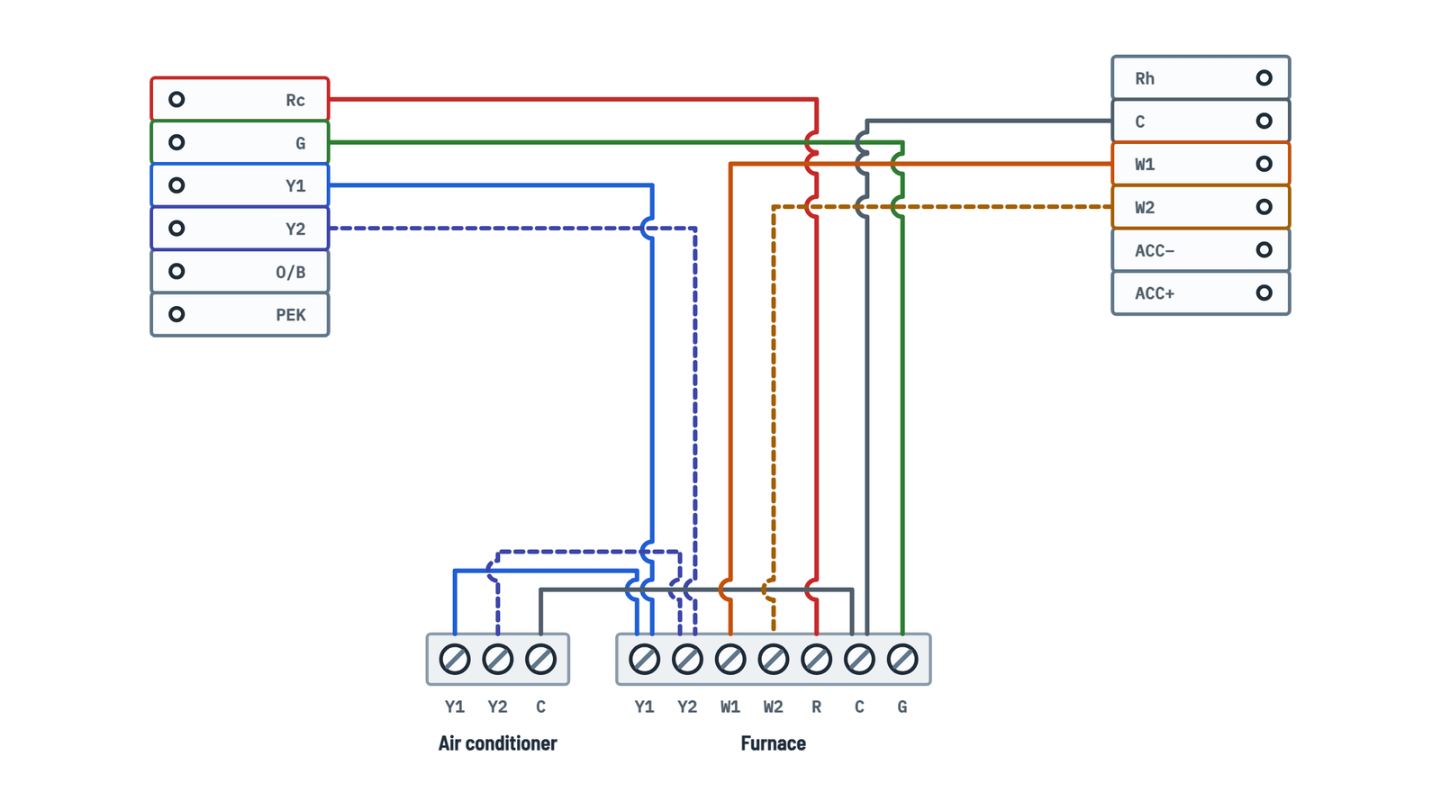
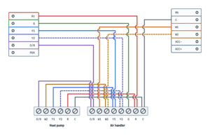
Conventional, heat pump with auxiliary heat, boiler with air handler and Power Extender Kit.
Terminals and components · 7
- Rc
- Rh
- C
- G
- Y1
- Y2
- O/B
- W1
- W2
- PEK
- Stage 2 (and O/B with a boiler), if applicable
In this system
Takes R from the furnace.
Rc and Rh
Do not jumper Rc and Rh: the ecobee joins them automatically when needed.
In this system
Takes R from the air handler; the heat pump takes R from the same strip.
Rc and Rh
Do not jumper Rc and Rh: the ecobee joins them automatically when needed.
In this system
Takes R from the air handler (cooling transformer).
Rc and Rh
Do not jumper Rc and Rh: the ecobee joins them automatically when needed.
In this system
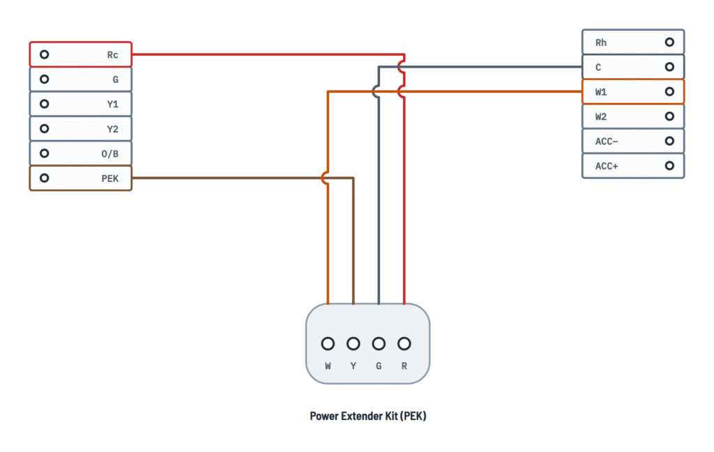
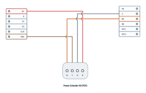
Takes the R wire from the PEK.
Rc and Rh
Do not jumper Rc and Rh: the ecobee joins them automatically when needed.
In this system
Furnace common; the air conditioner takes C from the same strip.
In this system
Air handler common; the heat pump takes C from the same strip.
In this system
Air handler common; it continues to the C of the air conditioner or heat pump.
In this system
Takes the PEK's G wire, which works as the common.
In this system
To the air handler's O/B and on to the heat pump's O/B.
In this system
Only if the outdoor unit is a heat pump: it goes straight to its O/B (dashed line).
In this system
To the furnace's W1.
In this system
Auxiliary heat: to the air handler's W1.
In this system
To the boiler's W1.
In this system
Takes the PEK's W wire.
In this system
To the furnace's W2.
In this system
To the air handler's W2, shared with the heat pump's W2.
In this system
To the boiler's W2.
PEK wires
PEK wire ecobee terminal R Rc G C Y PEK W W1 When to use it
Only if you have no C wire. The PEK is installed at the equipment, between the control board and the thermostat wires.
Humidifier, dehumidifier and ventilator
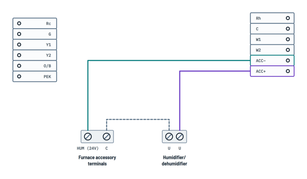
ACC+ and ACC− terminals for a 1-wire or 2-wire accessory.
Terminals and components · 1
- ACC+
- ACC−
Connection
ACC+ goes to the humidifier's second U; the first U goes to the furnace board's R.
Setup
On the thermostat screen, choose a 1-wire (ACC+) accessory.
Before
Remove the humidistat that controlled the humidifier: its U wires move to the ecobee and to the board's R, as shown.
Connection
ACC+ goes to the humidifier's second U.
Setup
On the thermostat screen, choose a 2-wire (ACC+, ACC−) accessory.
Connection
ACC+ goes to the ERV/HRV ventilator's G (HI/LO).
Setup
On the thermostat screen, choose a 2-wire (ACC+, ACC−) accessory.
Before
The R and G wires that went to the ventilator timer control now go to ACC− and ACC+.
Connection
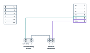
ACC− goes to the furnace's HUM (24 V) accessory terminal; C stays connected to the first U.
Existing wire
The gray dashed line (furnace C to the first U) is the existing wire: leave it as is.
Connection
ACC− goes to the ERV/HRV ventilator's R.
About This Diagram
These diagrams are redrawn from pages 66–75 of the Ecobee4 Thermostat manual, and we offer them completely free and in English. We have also categorized it in the Thermostats (HVAC & Water Heating) section on Diagramverse, and it has been rated by 1 user with an average rating of 5.0. If you have any specific questions about the Ecobee4 Smart Thermostat Wiring Diagram, we suggest checking the Frequently Asked Questions (FAQs) section.
Printable Ecobee4 Wiring Diagrams







Wiring Instructions
Before you start
The ecobee4 is a low-voltage thermostat built for 24VAC control circuits with a 2A maximum current. Take the cover off your old thermostat and look at its backplate. If it is marked 110 VAC, 120 VAC, 240 VAC or L1 and L2, or uses thick line-voltage wires, your system is not compatible. Millivolt systems are not compatible either.
Gather a small flathead screwdriver, a Phillips screwdriver, a pencil, a drill with a 3/16" bit for the drywall anchors, a hammer and, optionally, a wire stripper. Keep the supplied wire labels and a phone for photos on hand. You will normally reuse the existing thermostat cable. No wire gauge is specified for this thermostat. If you run new cable, standard solid-copper thermostat cable (commonly 18 AWG) is good practice.
Pick the diagram view that matches your equipment:
- Conventional: a furnace and air conditioner, with up to two stages of heat and cool.
- Heat pump: an air or geothermal heat pump with an air handler and optional auxiliary heat, using O/B.
- Boiler: boiler or radiant heat plus an air handler with cooling. The boiler has its own transformer and its own R wire, which goes to Rh.
- PEK: for systems with no C wire at the thermostat.
- Accessories: a humidifier, dehumidifier or ventilator on ACC+ and ACC−.
Swapping a thermostat is usually a homeowner job. Fitting the Power Extender Kit, though, means opening the furnace or air handler, where line voltage is present. If you are not comfortable working there, or local rules require it, hire a licensed HVAC contractor. Keep in mind that the warranty excludes units that were installed improperly or not installed by a licensed HVAC contractor.
Step-by-step wiring
- Turn off the HVAC system at its master switch or breaker. Call for heat or cooling at the old thermostat and wait a few minutes: no air should come from the vents. If you have a boiler, confirm the main flame is out.
- Remove the old thermostat cover and photograph the wires on its terminals.
- Check for a C wire. If you have one, you don't need the Power Extender Kit. If you don't, use the PEK variant, which needs R, G and Y/Y1, plus W/W1 if you have heat.
- PEK only: Open the HVAC cabinet and photograph the control board. Label only the R, Y or Y1, G and W or W1 wires that run to the thermostat, and ignore the wires going to the outdoor A/C. Move the labeled wires into the matching gray blocks on the PEK. Then connect the PEK's five white wires to the matching control-board terminals, including C. If wires land on both Rc and Rh at the board, you may have a two-transformer system, so contact ecobee support first. Mount the PEK without straining the wires and close the cabinet panel securely.
- At the wall, disconnect and label the wires one at a time. Leave any jumper on the old thermostat alone and label only the wires coming out of the wall. Remove the old base.
- Fit the trim plate if you need to hide old holes. Pull the wires through the backplate and fix it to the wall with the anchors and screws.
- Connect R first. A single R, Rc or Rh wire always goes into Rc. If you have two R wires, Rc goes to Rc and Rh goes to Rh. Never add a jumper between Rc and Rh.
- PEK only: Connect the thermostat's G wire to C and its Y wire to PEK, then W to W1 if you have one.
- Connect the remaining wires to their matching terminals: C, G, Y1, Y2, O/B, W1 and W2. Press the lever to open each block and insert the wire into the side of the block, not the front.
- Wire any accessory to ACC+ alone, or to ACC+ and ACC−, following the matching Accessories variant.
- Tug each wire gently. When a wire is seated, the lever on its block drops. Push excess cable back into the wall, seal the hole against drafts, and press the thermostat onto the backplate until it clicks and sits flush.
Testing and start-up
Turn the power back on at the switch or breaker. The screen should light up and guide you through setup and registration. Answer the equipment questions to match your wiring: set O/B to act as O or B, whichever your heat pump needs, and select 1-wire (ACC+) or 2-wire (ACC+, ACC−) for an accessory. Then test each mode by calling for heat, cooling and fan in turn, and confirm the right equipment starts. If you have a multimeter, a reading of roughly 24VAC between R and C at the control board confirms that the transformer is supplying power.
Safety notes
- Never connect the ecobee4 to 120 V or 240 V line voltage, or to a millivolt circuit.
- Keep the power off while the furnace or air handler cabinet is open, because it contains high-voltage wiring.
- Don't let bare R and C wires touch while the power is on. Many control boards protect the 24 V circuit with a fuse. If that fuse blows, replace it only with the rating printed on the board.
- Some old thermostats contain mercury. Don't break the capsule, and recycle the unit at a hazardous waste facility.
Troubleshooting
| Symptom | Probable Cause | What to Check |
|---|---|---|
| The screen stays blank after I turn the power back on | A wire isn't fully seated in its terminal block, or the breaker or HVAC switch is still off | Make sure the breaker or switch is back on. Pull the thermostat off the backplate, check that every lever has dropped, and tug each wire. Reinsert any loose wire into the side of the block. |
| Nothing powers on and the furnace seems dead too | The HVAC cabinet panel isn't fully closed, so the door safety switch keeps the system off | Reseat the furnace or air handler cover panel until it closes firmly, then check again. |
| I have a single R wire and the thermostat won't start | The R wire was put into Rh instead of Rc | Move the single R, Rc or Rh wire into the Rc terminal and leave Rh empty. |
| After installing the Power Extender Kit the screen is dark or the system acts strangely | The G and Y wires were swapped or left on G and Y1 at the thermostat | At the thermostat, R must go to Rc, G to C and Y to PEK. At the control board, check that each white PEK wire is on its matching terminal, including C. |
| The heat pump blows cold air when I call for heat | The reversing valve setting doesn't match the equipment | Make sure the O/B wire is on O/B, then switch the O/B setting on the thermostat between O and B and test heat and cool again. |
| The fan runs but there's no cooling | Y1 is loose at the thermostat or control board, or the outdoor unit's Y1 connection is open | Tug the Y1 wire at both ends. With the power on and cooling called, check for roughly 24VAC between Y1 and C at the board. |
| The blower won't run in fan-only mode | The G wire is missing or on the wrong terminal | Make sure the wire from the board's G terminal lands on G at the thermostat (or on C if you're using the PEK). |
| The boiler and AC behave erratically after the swap | A jumper was added between Rc and Rh, or the two R wires were swapped | Remove any jumper. Put the boiler's R wire on Rh and the air handler's R wire on Rc. |
| Nothing works and the control board fuse is blown | R touched C or another terminal while the power was on | Turn off the power, find and insulate the short, and replace the fuse with the rating printed on the board. |
| The humidifier or ventilator never turns on | The accessory type picked in setup doesn't match the wiring | In the thermostat settings, select 1-wire (ACC+) or 2-wire (ACC+, ACC−) to match how you wired it, and check the accessory wires. |
| The temperature reading is off by several degrees | Air is coming through the wall hole behind the thermostat | Push the excess cable into the wall and seal the hole so no draft reaches the sensor. |