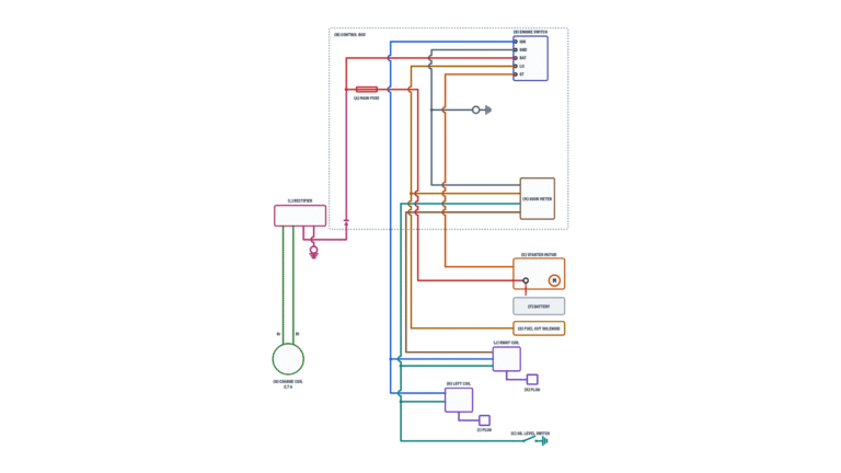
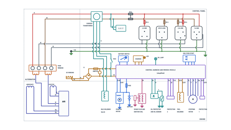
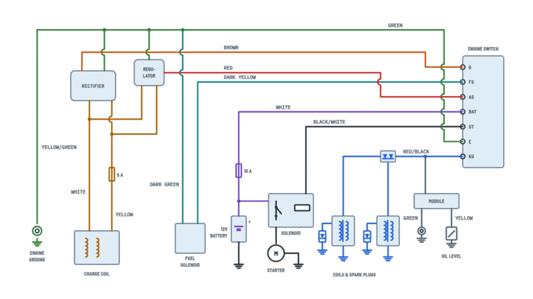
Duromax XP12000EH Generator Wiring Diagram
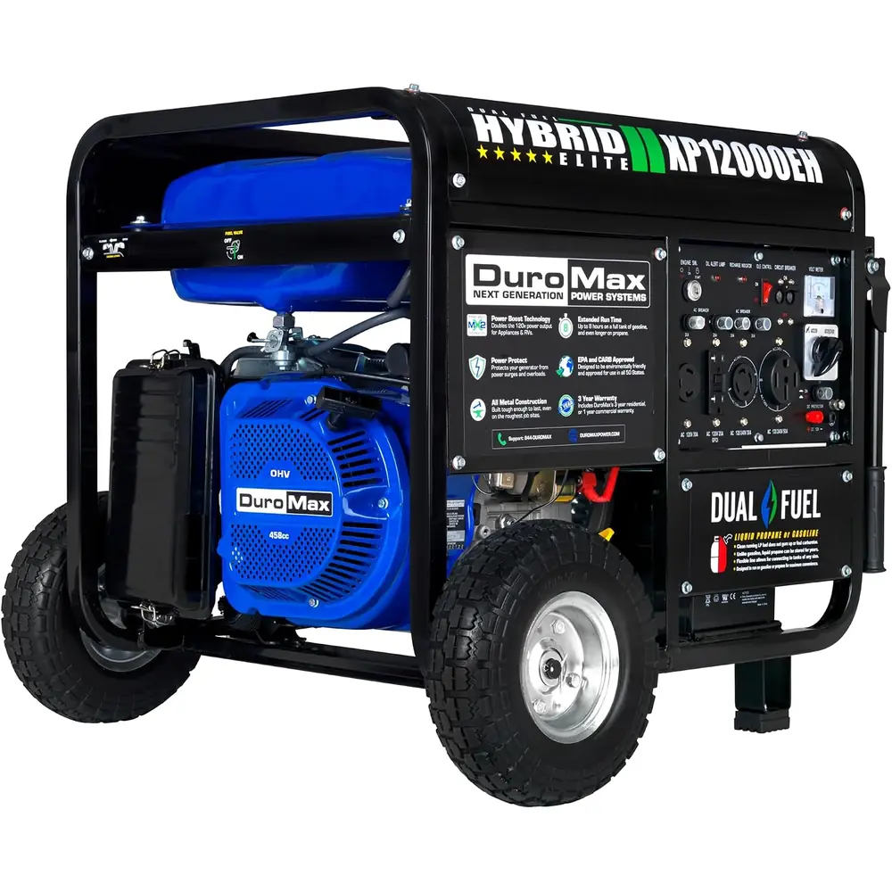
Generator wiring diagram
Alternator and AVR, voltage selector, four outlets with breakers, auto idle, DC output, starting and ignition.
Terminals and components · 21
- Stator
- R 240 V
- R 120 V
- Bl
- Neutral
- Ground
- AVR
- DC and fuel
- Starting
Wire colors
Code Color Bl Black Br Brown Br/R Brown/red Bu Blue LB Light blue Gr Gray O Orange R Red W White Y/G Yellow/green Bl/W Black/white Drawing
The selector's interior is shown simplified: only the terminals and their wires.
Caution
The DC output is for charging 12 V batteries only.
Switch positions
Position Connected terminals OFF IG to E and FS to G ON None: the engine runs START BAT to ST: operates the starter relay
About This Diagram
This diagram is redrawn from page 60 of the Duromax XP12000EH Generator manual, and we offer it completely free and in English. We have also categorized it in the Generators & Transfer Switches (Home Electrical) section on Diagramverse, and it has been rated by 1 user with an average rating of 5.0. If you have any specific questions about the Duromax XP12000EH Generator Wiring Diagram, we suggest checking the Frequently Asked Questions (FAQs) section.
Printable Duromax XP12000EH Wiring Diagrams
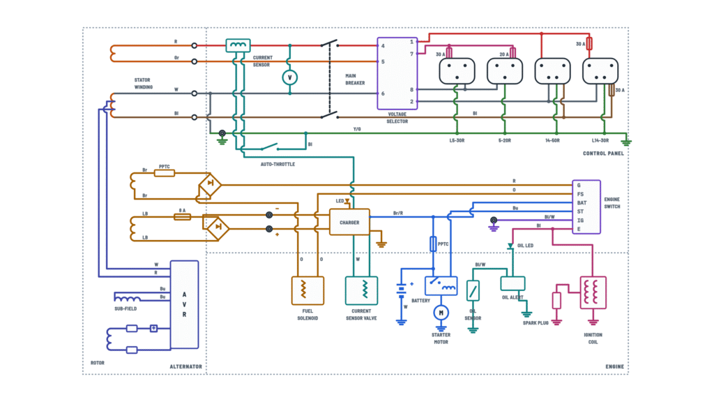
Wiring Instructions
Before you start
Most of the wiring on the Duromax XP12000EH happens outside the frame: the ground wire, the 12 V battery, the cords you make with the supplied plug ends, and the DC charging cables. The internal harness should only be opened to replace the carbon brushes or the AVR. Use one schematic for every unit. The only setting that changes how power reaches the outlets is the Voltage selector: the 120V ONLY position or the 120/240V position.
- Tools: the double-sided screwdriver and the 8, 10, 13 and 15 mm wrenches from the kit, a wire stripper, and a true-RMS multimeter rated for at least 300 V AC.
- Materials: No. 12 AWG stranded copper ground wire, a copper or brass ground rod, the supplied plug ends, and cord sized for the load and the length (see below).
- Isolation: before you touch any terminal, stop the engine, turn the key to OFF, switch the Main breaker off and disconnect the battery.
- Professional work: you need a qualified electrician, and usually a permit, before the generator feeds a building. That means a transfer switch or an interlock, never a cord plugged into a wall outlet. Grounding rules also vary by location, so ask a local electrician about yours.
Cord gauge by load (10 / 25 / 50 / 100 ft): 20 A needs 12 / 10 / 8 / 6 AWG. 30 A needs 8 / 6 / 4 / 4 AWG. 50 A needs 4 / 4 / 2 AWG up to 50 ft, and runs longer than that are not recommended.
Step-by-step wiring
- Ground the frame. Clamp the No. 12 AWG copper wire under the ground terminal nut and tighten it. Run the other end to a ground rod driven into the earth. Every outlet's Y/G pin is tied to this frame.
- Connect the battery. Connect the battery + lead first, then the negative. The battery + feeds the starter relay, and the Br/R charging wire passes through a PPTC on its way to the BAT terminal of the Engine switch. Tighten both posts firmly, because a loose battery lead is the most common reason the starter won't crank.
- Choose the voltage position. With the Main breaker OFF, set the selector to 120/240V if anything you will plug into the 14-50R or L14-30R needs 240 V. Choose 120V ONLY if every load is 120 V. In that position the two windings (R–Gr and W–Bl) work together, which doubles the 120 V current available and balances the load automatically.
- Make up cords with the supplied plug ends. On a 4-prong plug (L14-30P or 14-50P), connect one hot to each of X and Y, white to the neutral W blade and green to G. On the 3-prong 5-20P and L5-30P, connect the hot to the brass screw, white to the silver screw and green to ground. Strip only enough wire to seat it fully under the screw. Tighten the clamp on the cord jacket, not on the conductors.
- Size each cord for its outlet. The L14-30R, L5-30R and 5-20R each have their own 30 A or 20 A breaker. The 14-50R has no breaker of its own and sits directly behind the Main breaker, so its cord must be rated for 50 A.
- Connect DC charging cables, if you use them. Clip both cables to the battery you want to charge, then plug the positive cable onto the + post and the negative cable onto the − post. To disconnect, remove the cables from the generator first.
- Brush or AVR service only. Remove the two cover bolts and swap the part. Reconnect the two AVR wires to the brushes with the correct polarity: rotor R (+) and W (−). Then refit the cover.
Testing and start-up
- Unplug all loads. Leave the Main breaker OFF, open the fuel supply and turn the key to START. Crank for no more than 5 seconds at a time and wait 10 seconds between tries. Let the key spring back to ON or RUN.
- The panel Voltmeter sits between R and W, ahead of the Main breaker, so it should read about 120 V even with the breaker off.
- Turn the Main breaker on and measure at the outlets. Hot to neutral should read about 120 V, and in the 120/240V position hot to hot on the 4-prong outlets should read about 240 V. Neutral to ground should read close to 0 V, because W is bonded to ground at the stator.
- Connect the largest load first. In the 120/240V position, split 120 V loads as evenly as you can between the two hots.
- Check that the engine stops when you turn the key to OFF. If it keeps running, the ignition kill circuit (E to IG) or the Fuel solenoid valve circuit (FS to G) is not completing.
Safety notes
- The outlets carry 120/240 V and the panel terminals are live whenever the engine runs. Never work on the wiring with the engine turning.
- Only move the Voltage selector with the Main breaker OFF. Switching it under load can seriously damage the generator.
- Never back-feed a house through an outlet. It can energize utility lines and kill line workers.
- Never connect 50 Hz or 3-phase loads, and don't use the generator uncovered in rain or on wet ground. Plug in through a GFCI on metal decking or steelwork.
- Charging batteries give off explosive hydrogen. Wear goggles and gloves, and keep sparks and flames away.
Troubleshooting
| Symptom | Probable Cause | What to Check |
|---|---|---|
| The engine runs but none of the outlets have power | Main breaker is off or tripped, or the selector is not fully in one of its two positions | Turn the Main breaker off, set the selector firmly in 120V ONLY or 120/240V, then turn the breaker back on. Measure about 120 V from hot to neutral at the 5-20R. |
| A 240 V appliance hums or won't start on the 4-prong outlet | Selector left in 120V ONLY | With the Main breaker OFF, switch to 120/240V, then turn the breaker on. Measure about 240 V between the two hot blades of the L14-30R or 14-50R. |
| The voltmeter reads near zero and there is no output after brush or AVR work | AVR wires on the brushes reversed or loose, or the brushes are worn | Remove the generator cover and make sure rotor R (+) and W go to the correct brushes. Check brush length, since the brushes should be inspected every 250 hours. |
| Only the L5-30R or the 5-20R is dead while the other outlets work | That outlet's own 30 A or 20 A breaker has tripped | Unplug the load and reset that breaker. If it trips again, test the cord and the appliance for a short. |
| The main breaker trips in 120/240V mode even though total watts are under the rating | 120 V loads are all on one hot | Move some 120 V loads so they draw from the other hot. Keep the running total under 9500 W on gasoline or 8075 W on propane. |
| Tools bog down and lights dim at the end of a long cord | Cord gauge too small for its length | Check the cord against the gauge table. A 30 A load at 50 ft needs 4 AWG, and a 20 A load at 50 ft needs 8 AWG. |
| The key clicks or nothing happens at START | Battery discharged or a battery lead loose, the PPTC on the Br/R BAT feed has tripped, or the blue ST wire has come off | Measure about 12 V or more at the battery posts and tighten the leads. Check for 12 V on the blue wire at the relay while the key is held at START. Use the recoil start in the meantime. |
| The engine keeps running with the key at OFF | The black E wire or the IG ground (black/white) is broken or disconnected at the Engine switch | Stop the engine by closing the fuel valve. Then check for continuity between E and IG with the key at OFF, and check the black wire's connection at the ignition coil. |
| The engine starts and then dies within seconds, or won't start at all | Low oil, or the oil sensor's black/white wire is grounded and triggering the alert unit | Check the oil level on level ground (capacity 37 fl. oz). If the level is correct, inspect the oil sensor wire for chafing against the frame. |
| The 12 V DC posts are dead | 8 A DC breaker tripped | Disconnect the cables and reset the 8 A breaker. Use the posts only for 12 V automotive batteries, and never to jump-start a vehicle. |
| You feel a tingle when touching the frame or a plugged-in tool | Ground wire missing or loose, or a faulty cord ground | Stop the generator. Tighten the ground terminal nut and the clamp at the ground rod, then confirm continuity from each outlet's ground pin to the frame. |