Harbor Freight Predator 670 Engine Wiring Diagram
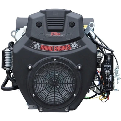
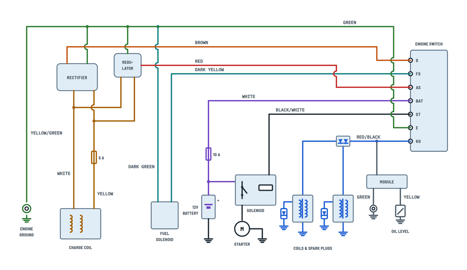
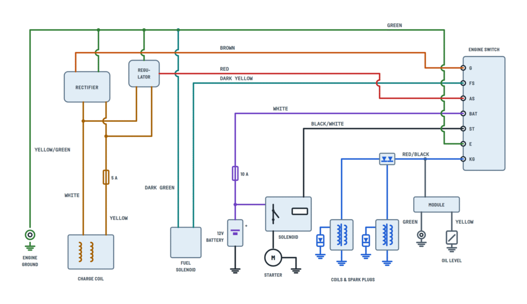
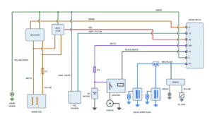
Complete electrical system
All the wires between the switch, charging, battery, starter and ignition.
Terminals and components · 11
- Ground
- Charging
- AS
- Fuel
- Battery
- Starter
- Ignition
Switch positions
Position Connects OFF KG – E ON AS – BAT · FS – G START ST – AS – BAT · FS – G Equipment ground
The engine ground terminal is used to ground the equipment it drives (for example, a generator).
Connector
When assembling the carburetor, line up the green wire with the green dot on the valve connector.
Cable gauge
Gauge (AWG) Max length 6 1,5 m (5 ft) 4 2,1 m (7 ft) 2 3,7 m (12 ft) Circuit breaker
If the panel circuit breaker keeps tripping, check the wiring and the starter.
Terminals
Coat the terminals and cable ends with a corrosion-preventive coating.
If it does not stop
A cut or disconnected red/black wire leaves the engine with no way to stop it with the key.
Will not start
Check the oil level: the low-oil shutdown prevents starting.
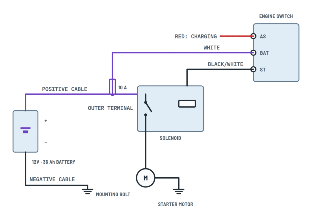
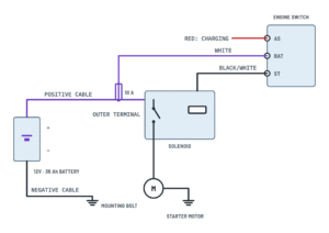
Battery and electric start
How the battery connects to the solenoid and what each switch terminal does when starting.
Terminals and components · 5
- Battery
- Starter and negative
- Charging
Switch positions
Position Connects OFF KG – E ON AS – BAT · FS – G START ST – AS – BAT · FS – G Cable gauge
Gauge (AWG) Max length 6 1,5 m (5 ft) 4 2,1 m (7 ft) 2 3,7 m (12 ft) Circuit breaker
If the panel circuit breaker keeps tripping, check the wiring and the starter.
Terminals
Coat the terminals and cable ends with a corrosion-preventive coating.
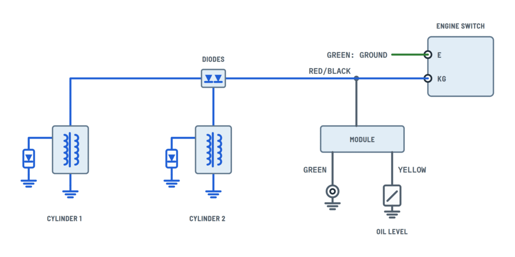
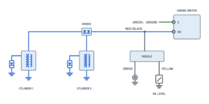
Ignition and low-oil shutdown
The red/black from KG shuts off both coils in OFF or when oil is low.
Terminals and components · 4
- Ignition
- Oil
- Ground
Switch positions
Position Connects OFF KG – E ON AS – BAT · FS – G START ST – AS – BAT · FS – G If it does not stop
A cut or disconnected red/black wire leaves the engine with no way to stop it with the key.
Will not start
Check the oil level: the low-oil shutdown prevents starting.
Equipment ground
The engine ground terminal is used to ground the equipment it drives (for example, a generator).
About This Diagram
These diagrams are redrawn from page 14 of the Predator 670 Engine manual, and we offer them completely free and in English. We have also categorized it in the Generators & Transfer Switches (Home Electrical) section on Diagramverse, and it has been rated by 1 user with an average rating of 5.0. If you have any specific questions about the Harbor Freight Predator 670 Engine Wiring Diagram, we suggest checking the Frequently Asked Questions (FAQs) section.
Printable Predator 670 Wiring Diagrams
Wiring Instructions
Before you start
First, pick the tab that matches your Predator 670's job. Use Complete if you are rewiring the harness or installing the engine on new equipment. Use Starter if the engine will not crank. It shows the battery cables, the white lead to BAT, the black/white lead to ST and the red charging lead to AS. Use Ignition if the engine will not stop or shuts down by itself. It shows the red/black kill circuit from KG, the oil level module and the common ground.
Have these ready before you begin:
- A fully charged 12V, 36 Ah lead-acid battery, set on a stable, flat surface near the engine.
- Battery cables sized for their length: 6 gauge up to 5 feet, 4 gauge up to 7 feet and 2 gauge up to 12 feet. A lower gauge number means a thicker cable, so if you are unsure, go thicker.
- Ring terminals, a proper crimper, heat-shrink tubing, a rubber boot for the positive terminal and a corrosion-preventive coating.
- A digital multimeter, insulated hand tools, safety goggles and work gloves.
- Spare fuses of the same ratings: 10 A for the white lead and 5 A for the charge coil's yellow lead.
Before you touch any wire, make these three things true: the engine is cool, the key switch is in OFF with the key removed, and both spark plug caps are off the plugs. Leave the battery negative cable disconnected until the last step. Do not install this engine on a vehicle; mount it on the equipment it is meant to drive, following that equipment's instructions. You do not need an electrical permit for this 12V system. If the ignition coils or the magneto seem faulty, have a qualified small-engine technician diagnose them.
Step-by-step wiring
- Ground first. Make sure the yellow/green common ground joins the engine ground terminal to the E terminal on the switch. The rectifier, the regulator and the fuel solenoid's dark green wire must also reach that ground. Every ground terminal should sit on clean, bare metal.
- Fuel solenoid. Connect the dark yellow wire to FS and the dark green wire to ground. If you unplugged the solenoid connector, plug it back in with the green wire lined up with the green dot.
- Charging circuit. Check that the charge coil's white and yellow leads reach the rectifier and the regulator, and that the 5 A fuse is in the yellow lead. Run the brown wire from the rectifier to G and the red wire from the regulator to AS.
- Ignition kill. Connect the red/black wire from KG through the two-diode block to both ignition coils. Do not bypass or remove the diode block. The oil level module also connects to the red/black wire; its yellow wire goes to the level sensor and its green wire to ground.
- Starter control. Run the black/white wire from ST to the small coil terminal on the starter solenoid. Route it away from the exhaust and from moving parts.
- Switch supply. Run the white lead from the outer solenoid terminal, through its 10 A fuse, to BAT.
- Positive cable. Connect the battery positive cable to that same outer terminal on the starter solenoid. Tighten it so it cannot work loose, and cover it with the boot.
- Negative cable. Bolt the negative cable securely to one of the engine mounting bolts. Make the connection at the battery negative post last of all.
- Protect the terminals. Coat all battery terminals and cable ends with corrosion-preventive coating.
Testing and start-up
- Check the switch first (battery still disconnected). Use the multimeter on continuity. In OFF, KG should show continuity to E. In ON, AS should show continuity to BAT, and G to FS, and KG should no longer show continuity to E.
- Check the battery. Connect the battery and measure across its posts. A fully charged 12V lead-acid battery normally reads about 12.6 V at rest. This is a general figure, not one specific to this engine.
- Test the fuel solenoid. Turn the key to ON. With the engine quiet, you can usually hear the fuel solenoid click.
- Prepare the engine. Check the oil level and make sure the engine sits level. Low oil, or a tilt that the oil sensor reads as low oil, will stop the engine from starting.
- Start the engine. Set the choke and the throttle as required. Hold the key in START for no more than a few seconds, then release it. The key should spring back to ON and the starter should stop at once.
- Check charging. With the engine running, measure the battery again. The voltage should be higher than your resting reading, which shows the charge coil, rectifier and regulator are charging the battery.
- Test the kill circuit. Turn the key to OFF. The engine must stop right away. If it keeps running, close the fuel valve and do not use the engine until you have fixed the KG circuit.
Safety notes
- The starter cable is not fused and carries a very high current. If a tool touches the positive terminal and the engine at the same time, it will spark, weld and can burn the harness. Keep the boot on the positive terminal and always remove the negative cable first.
- Connecting the battery backwards causes a short circuit or trips the circuit breaker. Check polarity before the last connection.
- If you leave the positive battery cable without a battery, wrap its terminal securely with electrical tape.
- Batteries give off explosive gas and contain sulfuric acid. Keep sparks and flames away, and wear eye protection.
- The ignition produces high voltage. Never hold a spark plug wire with wet hands. People with pacemakers should check with their doctor before working near the magneto.
- Test-run the engine only outdoors, away from windows, doors and vents. Its exhaust contains carbon monoxide.
Troubleshooting
| Symptom | Probable Cause | What to Check |
|---|---|---|
| Nothing happens when I turn the key to START, not even a click | Dead or disconnected battery, loose negative cable at the mounting bolt, blown 10 A fuse on the white lead, or tripped circuit breaker | Measure the battery; it should read about 12.6 V when charged. Check the negative connection at the mounting bolt for tightness and bare metal. Check the 10 A fuse, measure for battery voltage at BAT, and reset the circuit breaker. |
| The solenoid clicks but the starter barely turns or doesn't turn | Weak battery, cables too thin for their length, or loose or corroded connections | While cranking, compare the voltage at the battery posts with the voltage at the outer solenoid terminal. A large difference means a bad cable or connection. Check the cable gauge: 6 up to 5 feet, 4 up to 7 feet, 2 up to 12 feet. |
| The circuit breaker trips or the fuse blows as soon as I connect the battery | Battery cables reversed, or the white lead or the positive cable is chafed and touching metal | Check that the positive cable goes to the outer solenoid terminal and the negative to a mounting bolt. Inspect the white lead along its whole route. If the breaker keeps tripping, check the wiring and the starter motor. |
| The engine cranks but won't fire and the spark plugs come out dry | The fuel solenoid is not opening because of a loose dark yellow wire at FS, a missing dark green ground, or a connector plugged in the wrong way round | With the key in ON, listen for the solenoid click. Check that the green wire lines up with the green dot on the connector. Check continuity from the dark green wire to the engine block, and from G to FS in ON. |
| The engine cranks but there is no spark on either cylinder | The red/black KG circuit is grounded: a chafed wire, a faulty switch, the oil module reading low oil, or the yellow sensor wire shorted to ground | Check the oil level and make sure the engine is level. In ON, KG must not show continuity to E. Inspect the red/black and yellow wires for damaged insulation that touches metal. |
| Turning the key to OFF doesn't stop the engine | The red/black wire is broken or off KG, the diode block is open, or the E terminal has lost its ground | Stop the engine by closing the fuel valve. In OFF, check continuity from KG to E and from E to the engine block. Then trace the red/black wire through the diode block to both coils. |
| The engine starts, then shuts off after a few seconds or on uneven ground | Low oil shutdown from low oil, the engine being on a slope, or a fault on the oil module's yellow sensor wire | Fill the oil to the FULL mark with the engine level. Make sure the engine is mounted level. Inspect the yellow sensor wire and the module's green ground. |
| The battery slowly goes flat even though I run the engine regularly | No charging current: blown 5 A fuse on the charge coil's yellow lead, loose red wire at AS or brown wire at G, or a poor ground at the rectifier or regulator | Compare battery voltage with the engine off and running; it should rise when running. If it doesn't, check the 5 A fuse, the AS and G connections, the ground connections at the rectifier and regulator, and continuity from AS to BAT in ON. |
| The battery is dead after the equipment sat for a while | The key was left in ON, or the battery was left connected during storage | Always leave the key in OFF. Disconnect the battery cables, negative first, for storage, and recharge the battery once a month. |
| The starter keeps turning after I let go of the key | Stuck solenoid contacts, or the black/white wire is shorted to a powered wire | Disconnect the battery negative cable at once. Check that ST loses voltage when the key returns to ON. Inspect the black/white wire, and replace the solenoid if its contacts stay closed. |
| A battery terminal or cable gets hot or the insulation melts | A loose or corroded connection, or a cable too thin for its length | Clean the terminals down to bare metal, tighten them, and coat them with corrosion-preventive coating. Replace the cable with a thicker gauge that suits its length. |