Lutron Toggle TGCL-153P Dimmer Wiring Diagram

Complete diagram
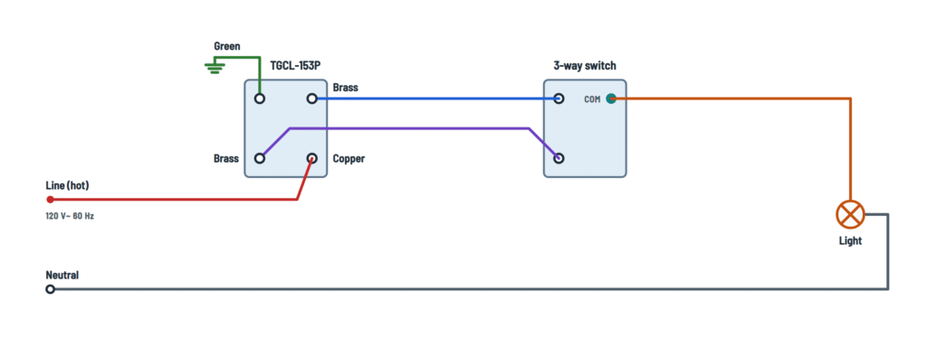
TGCL-153P wiring for one location or 3-way.
Terminals and components · 7
- Line
- To the light
- Lower brass
- Upper brass
- Neutral
- Ground
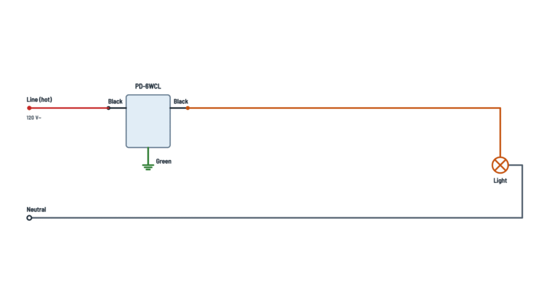
Single pole
The two bottom screws (brass and copper) are interchangeable: either one can take the hot.
How to connect it
Wrap the wire around the screw and tighten to 5 in-lbs (12 or 14 AWG wire), or strip 1/2 in (13 mm) and push it into the push-in terminal (14 AWG only).
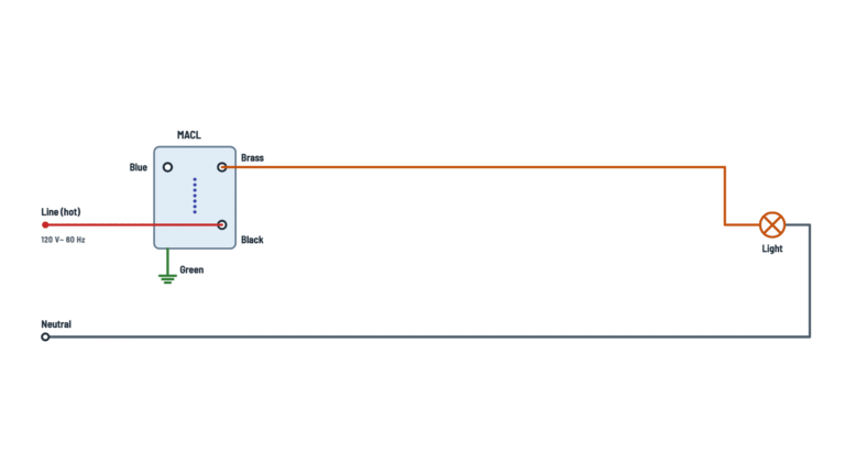
Marked wire
Before removing the old switch, mark the common wire (the one on the different-colored screw). That wire goes to the copper screw; it may be the line or the one going to the light.
How to connect it
Wrap the wire around the screw and tighten to 5 in-lbs (12 or 14 AWG wire), or strip 1/2 in (13 mm) and push it into the push-in terminal (14 AWG only).
In the box
If there are spliced neutrals in the box, leave them as they are.
Ratings
- Dimmable LED or CFL: up to 150 W
- Incandescent or halogen: up to 600 W
Ganged in one box
Removing side sections lowers the maximum incandescent wattage:
Sides removed None One Two Incand. & halogen 600 W 500 W 400 W Adjust the range for LEDs or CFLs
- Turn the lights on and move the slider to the bottom.
- Move the adjustment lever to improve dimming.
- Turn the lights off and on to verify.
Where it goes
To the wire going to the light.
Where it goes
To a traveler screw on the 3-way switch.
Single pole
Leave it unused.
Where it goes
To the other traveler screw on the 3-way switch.
Only one dimmer
Only one dimmer can be used in a 3-way circuit; the other location keeps a mechanical switch.
Where it comes from
From the lower brass screw.
Where it comes from
From the 3-way switch common.
If the box has no ground
It may be installed with a plastic faceplate and fasteners, or with the circuit protected by a GFCI. In that case, cap or remove the green wire.
About This Diagram
This diagram is redrawn from page 1 of the Lutron Toggle TGCL-153P Dimmer manual, and we offer it completely free and in English. We have also categorized it in the Light Switches & Dimmers (Home Electrical) section on Diagramverse, and it has been rated by 1 user with an average rating of 5.0. If you have any specific questions about the Lutron Toggle TGCL-153P Dimmer Wiring Diagram, we suggest checking the Frequently Asked Questions (FAQs) section.
Printable Lutron TGCL-153P Wiring Diagram


Wiring Instructions
Before you start
First work out which variant fits your installation. If Lutron Toggle TGCL-153P is controlled from one wall switch, use the Single pole variant. If it is controlled from two switches, use the 3-way variant. In that case the TGCL-153P replaces one of the two switches and the Existing 3-way switch stays at the other location. Only one dimmer can be used in a 3-way circuit, so do not put a second dimmer at the other end.
Check the load before you buy or install. The dimmer handles up to 150 W of dimmable LED or CFL lamps, or up to 600 W of incandescent or halogen lamps, at 120 V~ 60 Hz. If you remove the side sections to gang it with other devices, the incandescent/halogen rating drops to 500 W with one side removed and 400 W with both sides removed. Use it only with permanently installed fixtures. It must not control receptacles, motor-driven appliances or transformer-supplied appliances.
- Tools: insulated screwdrivers, wire stripper, a non-contact voltage tester or multimeter, electrical tape and a marker, and your phone for photos.
- Wire: the terminals accept 12 or 14 AWG copper. One of the connection methods shown on the package is marked for 14 AWG only. If your circuit is wired in 12 AWG, use the screw-terminal method rated for it. Strip 1/2 in (13 mm) of insulation.
- Permits and help: install in accordance with all national and local electrical codes. If you find a dead-end 3-way (black, red and white wires on the old switch, all from the same cable), aluminum wiring, or wiring you cannot identify, call a licensed electrician.
Turn off the circuit breaker or remove the fuse. Then confirm with your tester that every wire in the box is dead. Boxes sometimes contain more than one circuit.
Step-by-step wiring
- Remove the wallplate and unscrew the old switch, then pull it out without disconnecting anything. Photograph it and note which wire goes to which screw. If a wire is pushed into the back of the old switch, note which screw it is closest to.
- For a 3-way, find the wire on the darker screw (usually black, often marked COM). Wrap tape around it before you remove anything. This is the common wire. Do not confuse it with the ground wire on the green screw.
- If two wires share one terminal on the old switch, mark them and keep them together on the same dimmer terminal.
- Disconnect the old switch. Leave the bundle of capped neutral wires (usually white) in the back of the box untouched. The Neutral goes straight to the light and never connects to this dimmer.
- Connect the Green wire of the dimmer to the box Ground wire (bare or green) with a wire connector. If the box has no ground, cap the green wire. In that case you must use a plastic faceplate with plastic fasteners, or the circuit must be GFCI protected.
- Single pole: connect one switch wire to the Copper screw and the other to the Lower brass screw. These two bottom connections are interchangeable, so either wire can go to either screw. Leave the Upper brass screw unused.
- 3-way: connect the marked common wire to the Copper screw. Connect the two remaining wires (the travelers) to the Lower brass and Upper brass screws, in either order. At the other location, the Existing 3-way switch keeps its common and its two travelers as they were.
- Wrap each conductor clockwise under its screw head, or use the insert-and-twist method shown, and tighten to 5 in-lbs (0.55 N•m). Tug each wire to confirm it is secure and that no bare copper shows past the terminal.
- Fold the wires neatly into the box, mount the dimmer with its screws and fit the wallplate.
Testing and start-up
Restore power at the breaker. The toggle should turn the Light on and off, and the slider should vary the brightness smoothly. In a 3-way, both locations should turn the light on and off, but dimming works only at the TGCL-153P.
With LED or CFL lamps, set the dimming range:
- Turn the lights on and move the slider to the bottom.
- Turn the adjustment dial until the lamps stay lit at the lowest setting without flickering.
- Turn the lights off and on again to confirm they start reliably from the low setting.
If something is wrong, turn the breaker off before you open the box again. Use a multimeter only on a de-energized circuit for continuity checks, or have a qualified person take live readings.
Safety notes
- This is a 120 V AC device, and contact can cause serious injury or death. Always work with the breaker off and verify with a tester.
- Never connect any dimmer terminal to a neutral wire. Doing so permanently damages the dimmer.
- Do not exceed the derated wattage when ganging. Overloading causes overheating.
- It is normal for the dimmer to feel warm in use. If it is too hot to touch comfortably, turn it off and check the load.
- The dimmer is for indoor use only. Protect it from dust and paint while you finish the wall, and clean it only with a soft damp cloth, never with chemical cleaners.
Troubleshooting
| Symptom | Probable Cause | What to Check |
|---|---|---|
| The breaker trips or the dimmer stops working as soon as power is restored | A dimmer terminal was connected to a neutral wire, which can permanently damage the dimmer | Turn the breaker off and confirm that the white neutral bundle is capped together and not on any screw. If a neutral was connected, the dimmer is probably damaged and must be replaced. |
| The light never turns on from either switch in my 3-way setup | The common wire is on a brass screw and a traveler is on the Copper screw | Compare your photos of the old switch. The wire that was on the darker COM screw must go on the Copper screw, and the two travelers go on the Lower brass and Upper brass screws. |
| In a 3-way, the light only works when the other switch is in one position | A traveler is loose, or the common at the existing 3-way switch was disturbed | With the power off, check that both travelers are tight on the brass screws. At the Existing 3-way switch, check that its COM screw still holds the original common wire. |
| Nothing happens at all in a single-pole installation | One wire is on the unused Upper brass screw, or a connection is loose | Make sure the two switch wires are on the Copper and Lower brass screws, tightened to 5 in-lbs. Confirm the breaker is on. |
| Another switch or outlet nearby went dead after the install | Two wires that shared one terminal on the old switch were separated | Put both wires back together on the same dimmer terminal, or join them with a short pigtail under a wire connector. |
| LED lights flicker, buzz or turn off at the low end | The dimming range has not been adjusted, or the lamps are not dimmable or compatible | Turn the lights on, move the slider to the bottom and turn the adjustment dial until the light is steady. Confirm the lamps are marked dimmable. |
| The dimmer gets very hot or shuts off after a while | The load exceeds the rating, or it exceeds the derated value after removing side sections | Add up the lamp wattages. Stay under 150 W for LED/CFL. For incandescent/halogen, stay under 600 W, 500 W with one side removed or 400 W with both removed. |
| Light on a ceiling fan or a plug-in lamp misbehaves or hums | The dimmer is controlling a motor, a receptacle or a transformer-supplied appliance | Use the dimmer only for permanently installed dimmable lamps. Rewire so the fan, receptacle or transformer load is on a standard switch. |
| Both 3-way locations stopped working after a second dimmer was added | Two dimmers were installed in the same 3-way circuit | Only one dimmer is allowed per 3-way circuit. Put back a standard 3-way switch at the other location. |
| The wire keeps slipping out of the terminal | The strip length is wrong, or 12 AWG wire was used where only 14 AWG is allowed | Strip 1/2 in (13 mm), use the screw-terminal method rated for 12 AWG if you have heavier wire, and tighten to 5 in-lbs (0.55 N•m). |