Duromax XP13000EH Generator Wiring Diagram
Generator wiring diagram
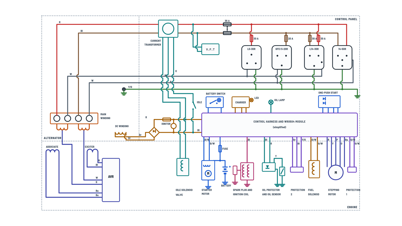
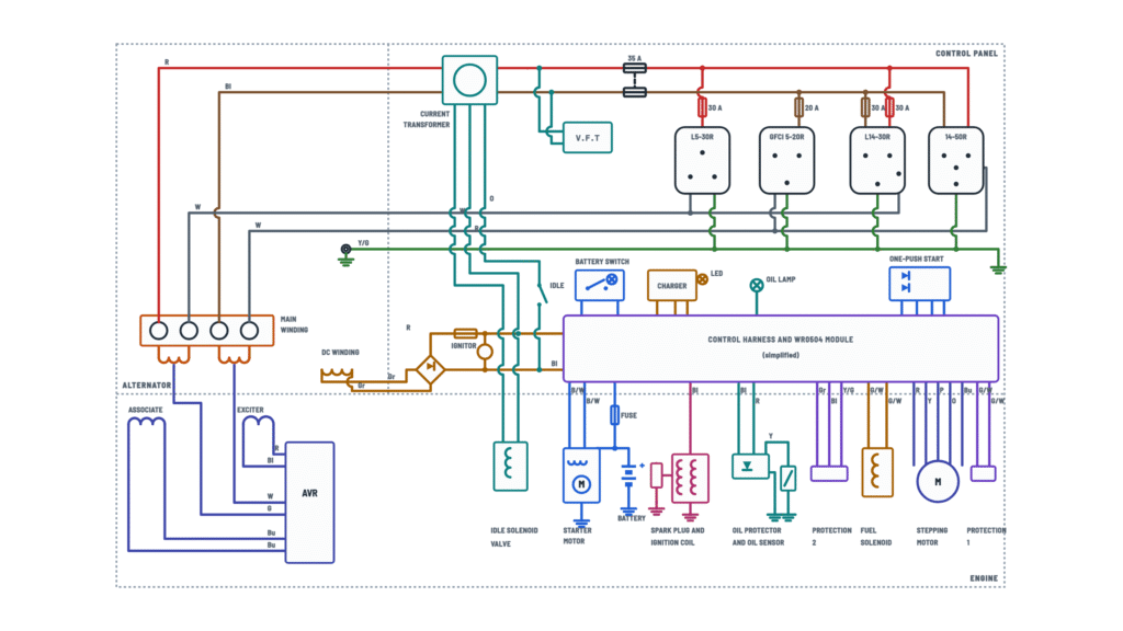
Alternator and AVR, outlets and protectors, idle, DC, control harness with the WR0504 module and engine components.
Terminals and components · 25
- Winding
- R
- Bl
- Neutral
- Ground
- AVR
- Idle and oil
- CC
- Control harness
- Starting
Wire colors
Code Color W White G Green R Red Bu Blue Gr Gray Br Brown Bl Black Y Yellow O Orange B/R Black/red Y/G Yellow/green B/W Black/white Use
The idle control lowers RPM with no load. Do not use it for home backup: voltage and frequency fluctuate.
Simplified drawing
In the manual's figure, these wires run along panel buses to the WR0504 module and the start button. Here they are drawn reaching the harness block, with their colors.
Simplified drawing
In the manual's figure, these wires run along panel buses to the WR0504 module and the start button. Here they are drawn reaching the harness block, with their colors.
Simplified drawing
In the manual's figure, these wires run along panel buses to the WR0504 module and the start button. Here they are drawn reaching the harness block, with their colors.
Simplified drawing
In the manual's figure, these wires run along panel buses to the WR0504 module and the start button. Here they are drawn reaching the harness block, with their colors.
Simplified drawing
In the manual's figure, these wires run along panel buses to the WR0504 module and the start button. Here they are drawn reaching the harness block, with their colors.
Simplified drawing
In the manual's figure, these wires run along panel buses to the WR0504 module and the start button. Here they are drawn reaching the harness block, with their colors.
Simplified drawing
In the manual's figure, these wires run along panel buses to the WR0504 module and the start button. Here they are drawn reaching the harness block, with their colors.
Simplified drawing
In the manual's figure, these wires run along panel buses to the WR0504 module and the start button. Here they are drawn reaching the harness block, with their colors.
Simplified drawing
In the manual's figure, these wires run along panel buses to the WR0504 module and the start button. Here they are drawn reaching the harness block, with their colors.
About This Diagram
This diagram is redrawn from page 60 of the Duromax XP13000EH Generator manual, and we offer it completely free and in English. We have also categorized it in the Generators & Transfer Switches (Home Electrical) section on Diagramverse, and it has been rated by 1 user with an average rating of 5.0. If you have any specific questions about the Duromax XP13000EH Generator Wiring Diagram, we suggest checking the Frequently Asked Questions (FAQs) section.
Printable Duromax XP13000EH Wiring Diagrams
Wiring Instructions
Before you start
Work out which job you are doing first. The Duromax XP13000EH diagram has one tab and covers the whole unit. The AC side runs from the main winding through the Main breaker to the four outlets. The 12 V side covers the Battery and starter motor, the DC winding, bridge and ignitor and the Control harness and WR0504 module. Most owners only ground the frame, build cords with the plug ends supplied with the generator, reconnect the battery, or replace the AVR or carbon brushes. Every internal connection should be put back exactly as the drawing shows. Do not reroute any of them.
- Tools: the double-sided screwdriver and spanners supplied with the unit (commonly 8, 10, 13 and 15 mm), a digital multimeter, wire strippers and a torque-limited screwdriver for the plug terminals.
- Grounding: No. 12 AWG stranded copper wire and a copper or brass ground rod driven into the earth. Grounding codes vary, so check the local rules.
- Cord gauge: size the cord for both current and length. A 30 A load needs 8 AWG at 10 ft and 6 AWG at 25 ft. A 20 A load needs 12 AWG at 10 ft and 10 AWG at 25 ft. Longer runs need heavier wire.
- Isolation: stop the engine, switch the Main breaker off, set the Battery switch to OFF and disconnect the battery. Let the engine and exhaust cool.
- Professional and permit: connecting the generator to a building's wiring needs a qualified electrician and a code-compliant transfer method. In most places that also means a permit. A direct connection without one can backfeed the utility lines and kill line workers.
Step-by-step wiring
- With the unit isolated, remove the generator cover (two bolts) if you are working on the alternator side. Photograph every connector before you unplug anything.
- Check the Main winding terminal block. The two 120 V windings (R–W and Bl–W) sit on the 4-terminal block. Their taps (G and W) go to the AVR. The unit has no voltage selector, so the 120/240 V output comes entirely from this arrangement.
- If you are replacing the AVR and auxiliary windings harness or the regulator, remove the two AVR bolts and unplug the wire clip. Then free the two AVR wires from the carbon brush. On reassembly, refit the AVR, reconnect the clip and fit the two brush wires with + and – the right way round.
- Confirm that the red and black lines still pass through the Current transformer and idle loop. Both lines must also reach the Multimeter (V.F.T) ahead of the breakers.
- Check that both poles of the Main breaker sit on the red and black lines. Then trace each outlet: the L5-30R takes red, the GFCI 5-20R takes black, and the L14-30R and 14-50R take both lines. Each outlet sits behind its own circuit protector, except the 14-50R, which is protected by the main breaker.
- Make sure both white neutral buses are tight. The Ground (yellow/green) must reach every outlet's ground pin and the frame. Keep neutral and ground separate at the outlets.
- Ground the frame. Tighten the grounding nut onto the No. 12 AWG wire and run the other end to the ground rod.
- When you build a cord, follow the terminal markings on the plug end. The two hots go to the brass terminals, the neutral to the silver terminal and the ground to the green screw. Use the cord gauge listed above. A 4-wire L14-30 cord needs four conductors; never leave out the neutral.
- Reconnect the battery last. Connect the positive cable to the starter relay feed first, then the negative cable. Check that the fuse on the white harness feed and the fuse on the red DC bridge output are both intact.
- Refit the generator cover and its two bolts before you run the engine.
Testing and start-up
Disconnect all loads and turn the Main breaker down. Set the idle control OFF. Turn the Battery switch ON; its lamp should light. Press the One-push start button for one second and release it. Never crank for more than 5 seconds; if the engine does not start, wait 10 seconds before trying again. Once it runs, the Battery charger LED should light. Hold the button for 3 seconds to stop the engine.
With the engine running and no load, use the MODE button to step through the Multimeter (V.F.T) readings. It should show about 220–240 V and about 60 Hz, each within ±10%. Then turn the main breaker up and measure at the outlets with your meter. You should read about 120 V from each hot to neutral, about 240 V between the two hots on the L14-30R and 14-50R, and 0 V from neutral to ground. Press TEST on the GFCI 5-20R: it must trip. Press RESET to restore it. Add loads largest first and keep the two lines as balanced as you can.
Safety notes
- Every outlet carries 120/240 V. The main winding and the AVR leads stay live whenever the engine turns, even with the breaker off.
- Do not use the idle control while the generator powers a house. Voltage and frequency swing widely in that mode.
- Never connect 50 Hz or 3-phase loads.
- The 12 V battery can deliver enough current to burn a wire or a tool. Keep the battery switch OFF during storage and whenever you service the unit.
- Run the generator outdoors only, with clearance on all sides. Keep it covered from rain and never touch bare wires or receptacles.
Troubleshooting
| Symptom | Probable Cause | What to Check |
|---|---|---|
| Engine runs but none of the outlets have power | Main breaker off or tripped, or the idle control is holding the engine at low speed | Turn the Main breaker up and set the idle control OFF. Then confirm the multimeter shows about 220–240 V and 60 Hz. |
| Engine runs but the multimeter shows little or no voltage after AVR or brush work | The brush wires are reversed, a connection is loose or the AVR clip is unplugged | With the engine stopped, check the AVR wire clip and the two brush wires. Fit + and – correctly and make sure the brushes are not worn. |
| Only the GFCI 5-20R is dead; the other outlets work | The GFCI has tripped or its 20 A protector has opened | Press RESET on the GFCI and reset its circuit protector. If it trips again at once, unplug the load and look for a damp cord or a fault in the appliance. |
| The L5-30R is dead but the GFCI works, or the other way round | Each outlet is on a different line, red or black, and has its own protector | Reset the 30 A protector on the L5-30R. Measure from red to white to confirm about 120 V. |
| Lights flicker or the breaker trips early in 120/240 V use | Most of the load is on one line | Spread the 120 V loads between the red-line and black-line outlets. Check that the total running load stays under 10500 W on gasoline or 9975 W on propane. |
| A 240 V appliance hums but will not start on a homemade cord | One hot conductor is open or swapped with the neutral at the plug | Measure at the cord end: you should read 240 V between the two hots and 120 V from each hot to neutral. Rewire the plug to its terminal markings. |
| Equipment runs weak and the cord gets warm | The cord is undersized for its length and load | Compare the cord with the gauge table. A 30 A load needs 8 AWG at 10 ft and 4 AWG at 50 ft. |
| A slight shock or tingle from the frame or a tool | The ground wire is missing or loose, or neutral and ground are swapped in a cord | Tighten the grounding nut and the No. 12 AWG wire to the rod. Check with an ohmmeter that each outlet ground pin is continuous to the frame, and that you read 0 V from neutral to ground. |
| Pressing the start button does nothing | Battery switch OFF, battery disconnected, or the fuse on the white harness feed has blown | Set the Battery switch ON and check that its lamp lights. Measure about 12 V at the battery, then test the fuse. |
| Battery is flat after storage or the charging LED never lights | Battery switch left ON, or an open in the DC winding circuit or its fuse | Turn the switch OFF for storage. With the engine running, check that the charger LED lights. If it stays off, test the fuse on the red DC bridge output. |
| Engine cranks but will not fire, or stops soon after starting | Low oil shutdown, or a loose ignition coil or oil protector wire | Check the oil level on the dipstick, then check the black ignition wire and the yellow oil sensor connection at the protector unit. |