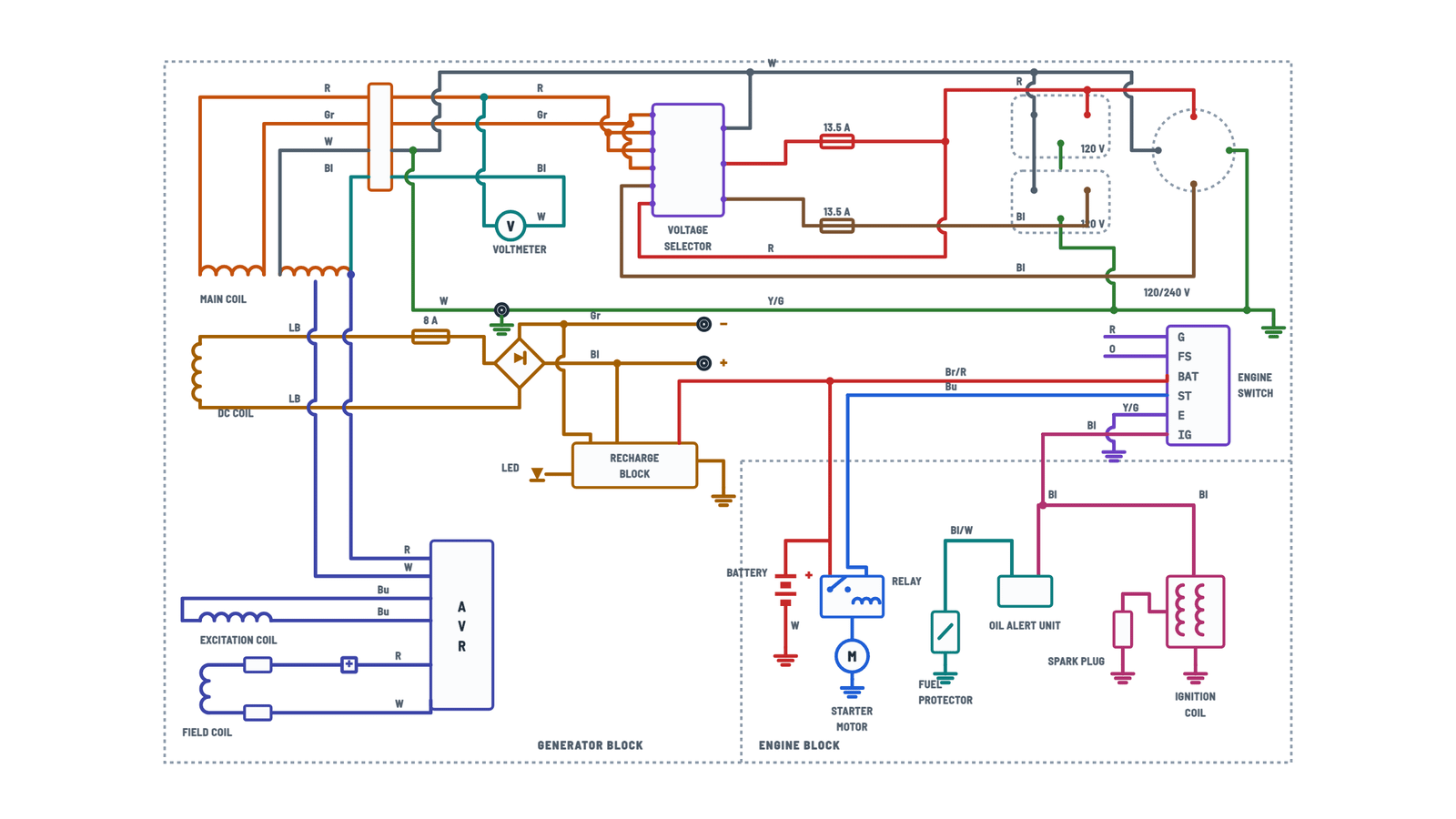
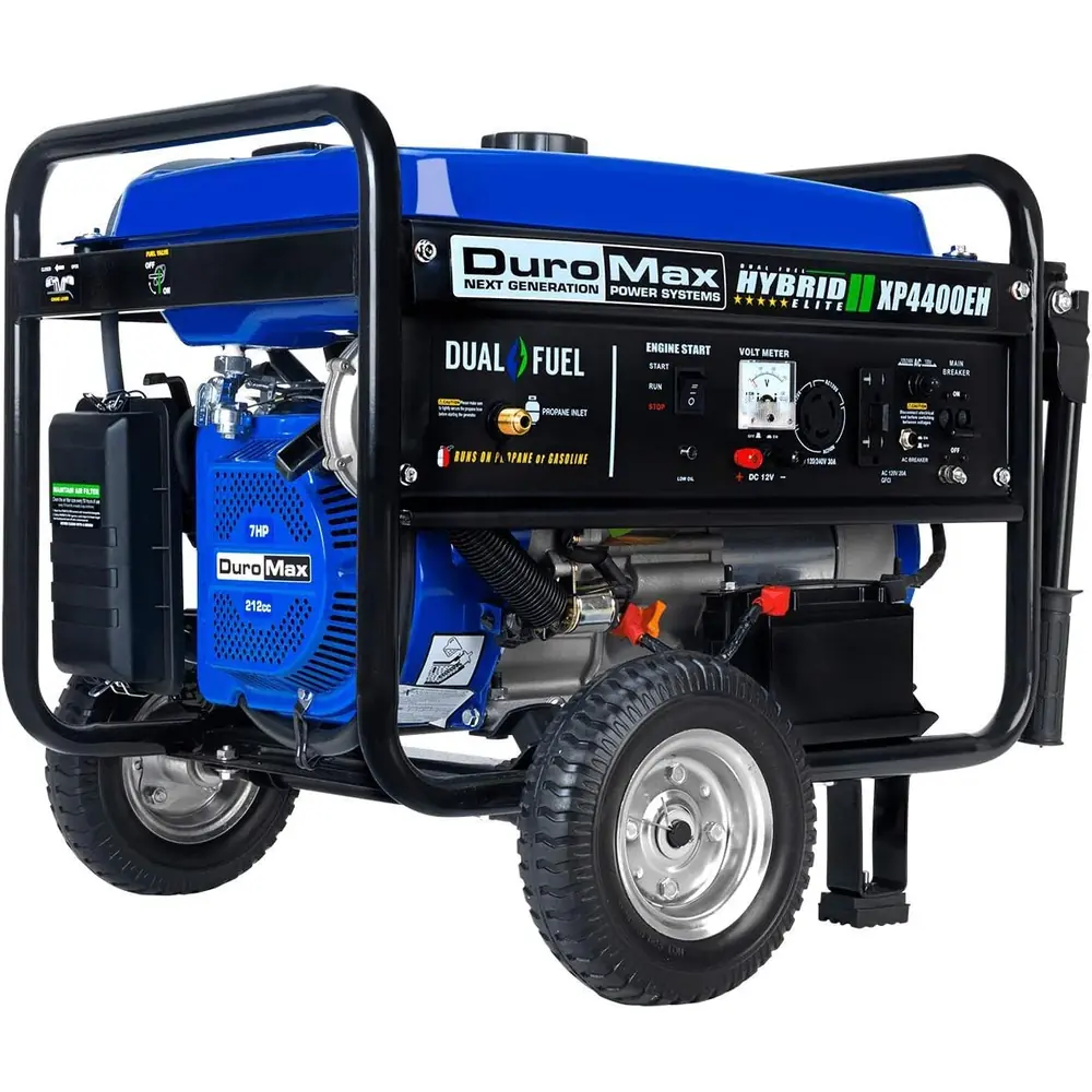
Duromax XP4400EH Generator Wiring Diagram
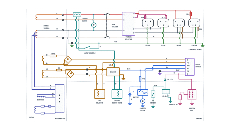
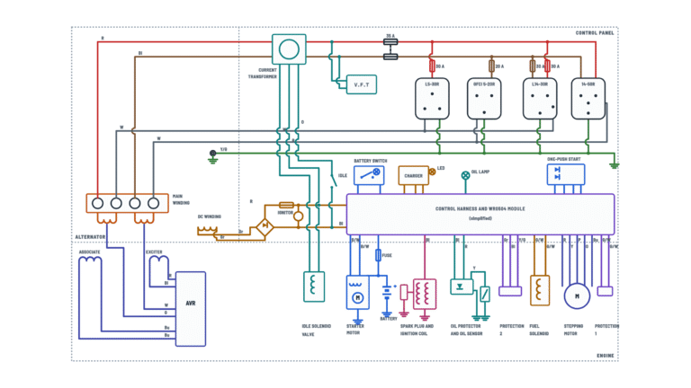
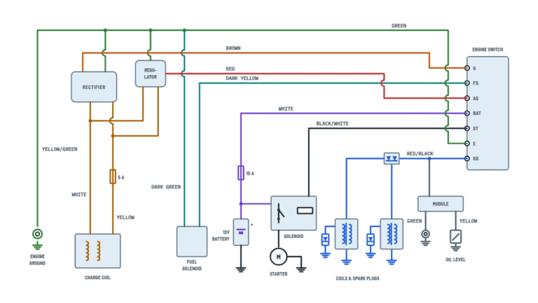
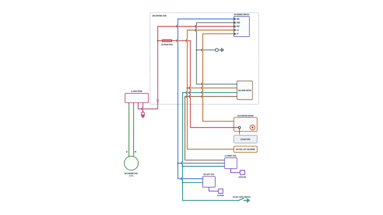
Generator wiring diagram
Coils, AVR, voltage selector, outlets, DC output, battery charging, electric start and ignition.
Terminals and components · 17
- Main coil
- Line 1
- Line 2
- Neutral
- Ground
- AVR
- DC and charging
- Starting
- Ignition
Wire colors
Code Color Bl Black Br/R Brown/red Bu Blue LB Light blue Gr Gray Y/G Yellow/green O Orange R Red W White Bl/W Black/white Warning
Only change the selector with the main breaker OFF: switching under load can damage the generator.
Drawing
The selector's interior is shown simplified: only its input and output wires.
Check
The manual's panel description lists a 120 V GFCI outlet with a 20 A breaker and a 10 A DC breaker; the schematic shows two 13.5 A breakers and an 8 A fuse. Check the ratings on your panel.
Caution
The DC output is only for charging 12 V automotive batteries; never use it to jump-start a vehicle.
Switch positions
Position Connected terminals OFF IG to E and FS to G: ignition is cut ON None: the engine runs START BAT to ST: operates the starter relay G and FS terminals
In the schematic, the connector's red (G) and orange (FS) wires do not reach any component.
About This Diagram
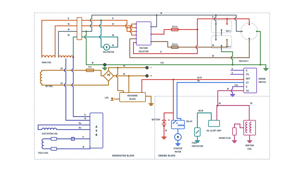
This diagram is redrawn from page 74 of the Duromax XP4400EH Generator manual, and we offer it completely free and in English. We have also categorized it in the Generators & Transfer Switches (Home Electrical) section on Diagramverse, and it has been rated by 1 user with an average rating of 5.0. If you have any specific questions about the Duromax XP4400EH Generator Wiring Diagram, we suggest checking the Frequently Asked Questions (FAQs) section.
Printable Duromax XP4400EH Wiring Diagrams
Wiring Instructions
Before you start
Work out which part of the generator you are wiring. The Duromax XP4400EH diagram covers three separate systems. The AC output side has the Main coil, Voltage selector, Line 1 (red), Line 2 (black), Neutral (white), Ground (yellow/green) and the Voltmeter. The excitation side has the Excitation coil, the Automatic voltage regulator (AVR) and the Field coil (rotor). The 12 V side has the 12 V battery, Starter relay and motor, Engine switch, Recharge block, 12 V DC output, Oil alert and fuel protector, and the Ignition coil and spark plug. Most owners only connect the ground, the battery, cords and the DC charging leads. Brushes, the AVR and the coils are service work.
Tools: the supplied screwdriver and wrenches (10/12 mm and 13/15 mm), a multimeter that reads AC volts, DC volts and continuity, a wire stripper, safety goggles and rubber gloves for battery work. Materials: No. 12 AWG stranded copper grounding wire and a copper or brass ground rod. If you are building cords, you also need the supplied plug ends and cord sized from the gauge table below.
Isolate everything first: stop the engine and let it cool. Set the Engine switch to OFF, flip the main breaker down, pull the spark plug cap and disconnect the battery negative. Never connect the generator to a building's wiring yourself. A house connection needs a qualified electrician, a transfer device that prevents backfeed onto utility lines, and usually a permit.
Step-by-step wiring
- Ground the frame. Tighten the grounding nut onto a No. 12 AWG stranded copper wire. Run the other end to a copper or brass rod driven into the earth. Grounding rules vary by location, so confirm local requirements with an electrician.
- Connect the starting battery. The 12 V battery ships with its negative cable loose. One end of that cable is already grounded. Route the free end to the battery's negative terminal, fasten it with the battery's screw and nut, and slide the black rubber boot over it. Check that the red + lead is tight. It feeds the Starter relay and, through the brown/red wire, the BAT terminal of the Engine switch and the Recharge block.
- Set the Voltage selector with the main breaker OFF. Choose 120/240V if any 240 V device will use the 4-prong twist-lock outlet. Choose 120V ONLY when every load is 120 V. This doubles the 120 V current and balances the windings automatically.
- Build or inspect your cords. On an L14-30 plug, connect X to one hot conductor, Y to the other hot conductor, W to the white neutral and G to the green ground. On a 5-20 plug, keep white on the neutral blade and green on the ground pin. Size the cord from the current and length: a 20 A load needs 12 AWG at 10 ft, 10 AWG at 25 ft and 8 AWG at 50 ft. A 30 A load needs 8 AWG at 10 ft, 6 AWG at 25 ft and 4 AWG at 50 or 100 ft. Longer 30 A runs are not recommended.
- Connect DC charging leads in order. Clamp the charging wires to the external battery's + and − terminals first. Next, plug the positive wire into the positive DC post. Start the generator, then connect the negative wire to the negative post. When you finish, unplug the leads from the generator first to avoid a spark at the battery.
- Reconnect brushes or the AVR during service. When you replace the carbon brushes or the AVR, put the two AVR wires back on the brushes with the correct polarity: red (+) and white. Reseat the AVR wire clip and confirm the two blue Excitation coil wires are secure. Inspect the brushes every 250 running hours.
Testing and start-up
- With the engine off, check continuity between the outlets' ground pins and the frame. You should read close to 0 ohms.
- With the Engine switch at OFF, IG should have continuity to E. At ON, that connection must open, otherwise the ignition stays grounded and the engine will not fire.
- Measure the battery at its posts. A charged 12 V battery normally reads about 12.6 V.
- Unplug every load and leave the breaker down, then start the engine. Crank for no more than 5 seconds at a time and wait 10 seconds between tries.
- Once the engine runs smoothly, check the Voltmeter, then flip the breaker up. Measure about 120 V between each hot and neutral at the outlets. In 120/240V, measure about 240 V between X and Y on the twist-lock. The charging LED on the Recharge block should light.
- Plug in the largest load first and spread loads as evenly as you can between the two lines.
Safety notes
- The outlets carry 120/240 V whenever the engine runs and the breaker is up. Do not touch bare wires or receptacles.
- Changing the Voltage selector with the breaker ON can seriously damage the generator.
- Neutral (white) is bonded to ground inside the generator. Tell your electrician this before any connection through a transfer switch.
- Use a GFCI on wet ground, metal decking or steelwork. Do not run the generator uncovered in the rain.
- Run the generator outdoors only, well away from openings, because the exhaust contains carbon monoxide.
- Charging batteries give off explosive hydrogen. Wear goggles and gloves, and keep flames and cigarettes away.
- Keep the total running load below the rated wattage on the label: 3500 W on gasoline or 3325 W on propane.
Troubleshooting
| Symptom | Probable Cause | What to Check |
|---|---|---|
| Engine runs and the Voltmeter shows voltage, but nothing comes out of the outlets | Main breaker still down, or a 13.5 A line breaker has tripped | Flip the main breaker up and reset any tripped line breaker. Then measure about 120 V between hot and neutral at each outlet. |
| Engine runs but the Voltmeter reads zero and no outlet has power | No field current: worn carbon brushes, brush wires reversed or loose, AVR clip unplugged, or a damaged AVR | With the engine off and the battery negative disconnected, check that the brush wires are connected red to + and white to the other brush. Also check that the AVR clip is seated, the two blue Excitation coil wires are tight and the brushes are not worn. Replace the AVR if it overheated or was overloaded. |
| My 240 V tool hums or won't run on the twist-lock outlet | Voltage selector left in 120V ONLY | Stop the loads, flip the main breaker down and switch to 120/240V. Then turn the breaker back on and measure about 240 V between X and Y. |
| One duplex outlet works and the other is dead | The breaker on that line has tripped, or Line 1 (red) or Line 2 (black) is loose at the receptacle | Reset the breaker. If it is still dead, shut down, remove the spark plug cap and the battery negative, and check that the red or black wire is tight at the receptacle. |
| The breaker trips even though the total load is under the rating | Load piled onto one line, or a 240 V cord wired with X and Y on the same hot | Move loads so both lines carry about the same current. Check the cord plug: X and Y must go to different hot conductors, and W only to white. |
| Nothing happens or I only hear a click when I press START | Battery negative never connected, a loose + lead at the Starter relay, a broken blue ST wire, or a flat battery | Make sure the negative cable is fastened. Measure about 12.6 V at the battery. With the switch held at START, check continuity between BAT and ST and for 12 V on the blue wire at the relay. |
| The engine cranks but never fires, or stalls seconds after starting | Low oil, so the Oil alert grounds the black IG wire, or a chafed IG or black/white wire touching the frame | Check the oil level on a level surface. With the switch at ON, there must be no continuity between the IG wire and ground. Inspect the IG and black/white wires for damaged insulation. |
| The engine keeps running when I switch it OFF | The IG wire is broken between the switch and the Ignition coil, or the switch's E terminal is not grounded | Stop the engine by closing the fuel valve. Then check continuity between IG and E with the switch at OFF, and between E and the frame. |
| The starting battery goes flat and the charging LED never lights | The 8 A fuse on the DC coil has blown, or the brown/red wire from the Recharge block is loose | Check the fuse and the brown/red connection to the battery. With the engine running, battery voltage should rise above its resting value. |
| I get no output at the DC posts | The 10 A DC breaker has tripped, the 8 A fuse has blown, or the charging leads are reversed | Reset the DC breaker, check the fuse and confirm that + goes to + and − goes to −. Use the posts only to charge a 12 V battery. |
| I feel a tingle when I touch the frame or a tool | Missing or loose ground wire, a damaged cord, or a loose yellow/green conductor | Shut down and check continuity from the outlet ground pins to the frame and from the frame to the ground rod. Replace any cord with cut insulation. |
| Lights dim and motors bog down at the end of an extension cord | Cord gauge too small for its length and current | Compare the cord with the gauge table, for example 10 AWG for 20 A at 25 ft. Use a heavier or shorter cord. |