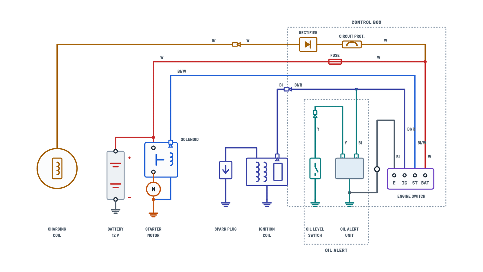
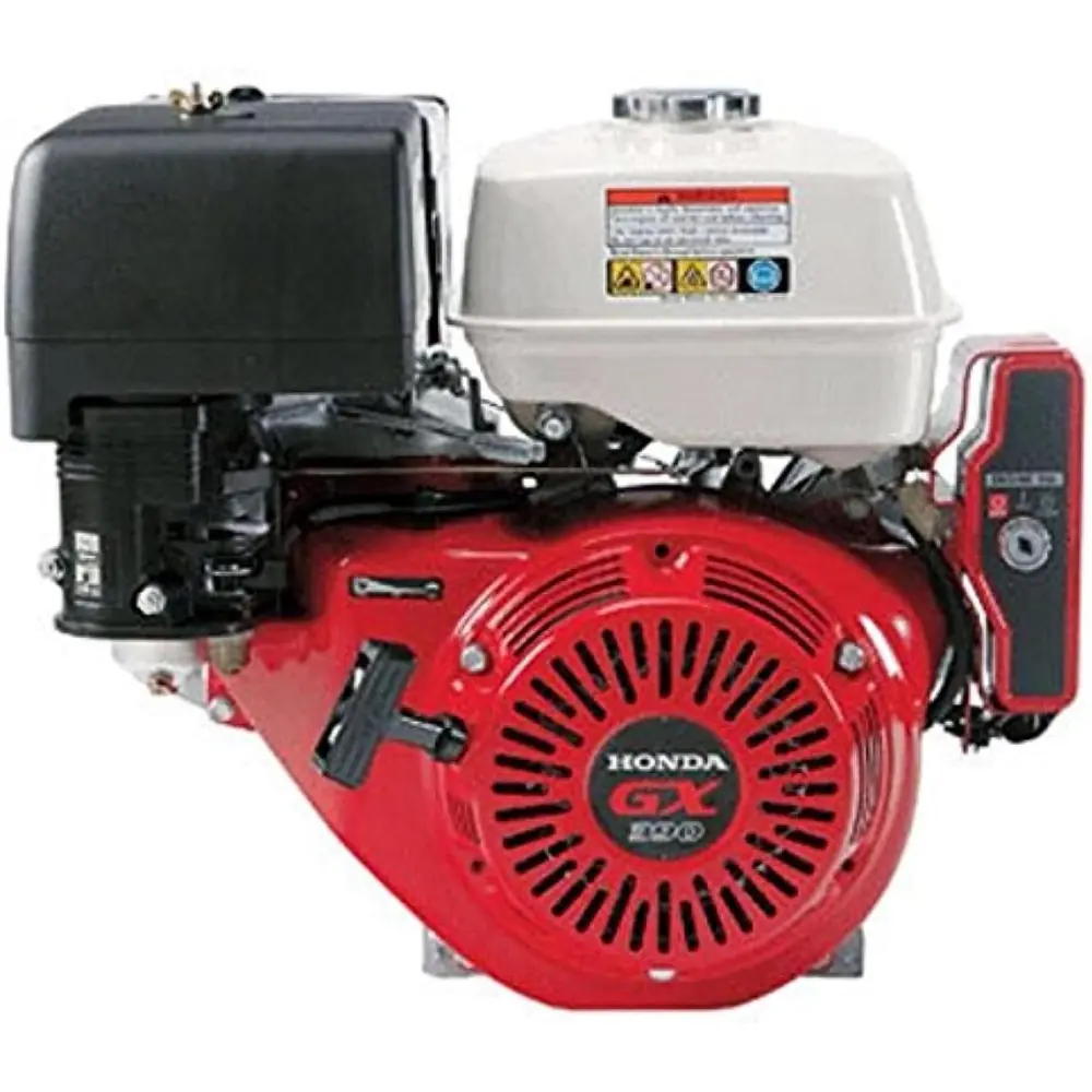
Honda GX390 Generator Wiring Diagram
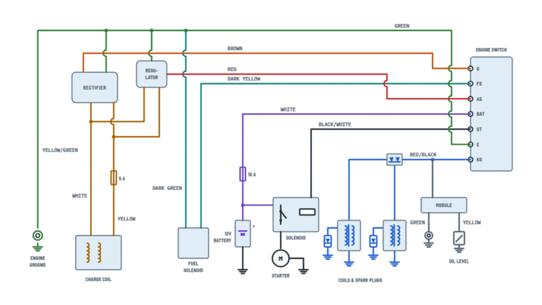
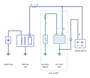
Engine wiring diagram
Ignition, oil alert, engine switch and, on electric starter models, charging and starting.
Terminals and components · 13
- +12 V
- Charging
- Solenoid
- Starter motor
- Ignition
- Oil alert
- Switch
- Ground
Positions
Position Connected terminals OFF E to IG: the ignition coil is grounded ON None: the engine can run START ST to BAT: feeds the solenoid Wire colors
Code Color Bl Black Y Yellow W White Gr Gray Bl/W Black/white Bl/R Black/red Positions
Position Connected terminals OFF E to IG: the ignition coil is grounded ON None: the engine can run Wire colors
Code Color Bl Black Y Yellow W White Gr Gray Bl/W Black/white Bl/R Black/red Oil alert
The same wire goes to the oil alert unit, which grounds it when the oil is low.
Spark plugs
Brand Model NGK BPR6ES DENSO W20EPR-U If the engine stops
If it stops and will not restart, check the oil level first.
If it trips
The green indicator pops out. Find and fix the cause before pushing the button to reset it.
Connection order
Connect the positive cable first, then the negative. Do not reverse the polarity: it short-circuits the charging system.
About This Diagram
This diagram is redrawn from page 19 of the Honda GX390 Generator manual, and we offer it completely free and in English. We have also categorized it in the Generators & Transfer Switches (Home Electrical) section on Diagramverse, and it has been rated by 1 user with an average rating of 5.0. If you have any specific questions about the Honda GX390 Generator Wiring Diagram, we suggest checking the Frequently Asked Questions (FAQs) section.
Printable Honda GX390 Wiring Diagrams
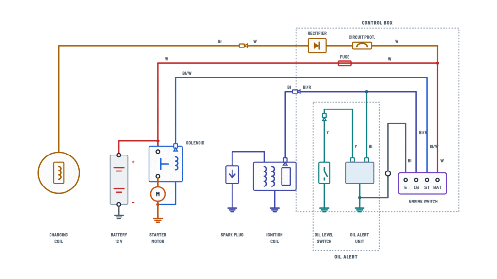

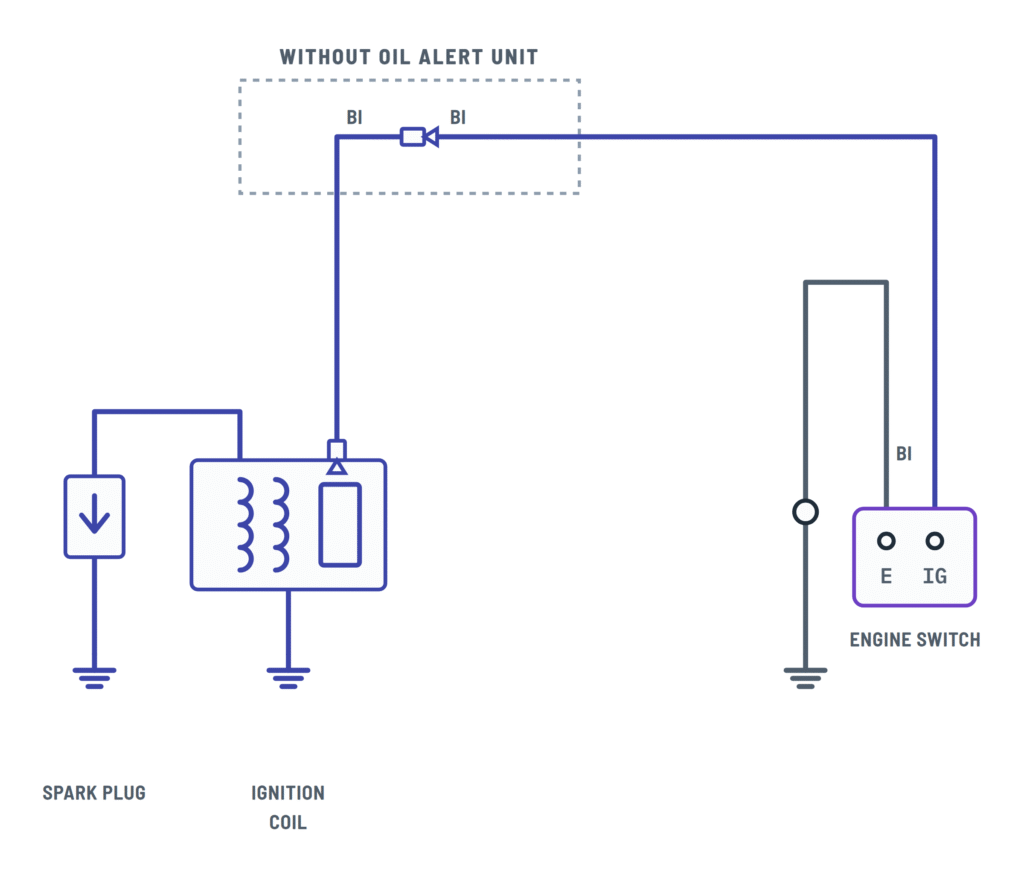


Wiring Instructions
Before you start
The Honda GX390 diagram covers the engine's own low-voltage wiring: the stop circuit, the ignition, the Oil Alert system, battery charging and the electric starter. It does not cover the AC output side of the generator head (the alternator, outlets and breakers). For those, use the generator manufacturer's documentation.
First, choose the variant that matches your engine:
- Electric starter: the engine switch is a key switch with a START position, and the engine has a 12 V battery, a starter solenoid, a starter motor, a fuse and a circuit protector.
- Without electric starter: you start the engine with the recoil handle only. The switch has just OFF and ON, joining E and IG at OFF.
- Without oil alert: no yellow wire comes from an oil level switch on the crankcase, and no Oil Alert unit is in the stop circuit.
Tools and materials: a multimeter with a continuity or ohms range, a 21 mm spark plug wrench, a wire-type feeler gauge, terminal crimpers, eye protection and gloves for battery work, and dielectric or terminal grease. For battery cables and any replacement leads, use at least the same gauge as the original wire. Never use thinner wire. If you are unsure about the gauge, match the factory cable or check with a Honda dealer.
Isolation: set the engine switch to OFF, set the fuel valve lever to OFF, and pull the spark plug cap so the engine cannot start by accident. Let the engine and muffler cool. On electric-start engines, disconnect the battery before you touch the starter wiring. If the generator feeds a building, you need a transfer switch installed by a licensed electrician, and local rules may require a permit. The engine wiring itself does not need one.
Step-by-step wiring
- Ground the E terminal. Run the black (Bl) wire from terminal E on the engine switch to a clean, bare-metal engine ground. This is the reference for the whole stop circuit.
- Connect the ignition coil's stop wire to IG. Connect the coil's black wire to the IG terminal. On electric-start engines it reaches IG as black/red (Bl/R); on the other variants it goes straight to IG. Never cut or insulate this wire: it is the only way the switch stops the engine.
- Connect the Oil Alert circuit (if fitted). Plug the yellow (Y) wire from the oil level switch into its connector and route it to the Oil Alert unit. The unit ties into the coil wire and grounds it when the oil is low, so the engine stops even with the switch at ON. Make sure the connector is fully latched and away from the muffler.
- Fit the spark plug. Use a BPR6ES or W20EPR-U plug with a gap of 0.7–0.8 mm. Thread it in by hand, then tighten it with the 21 mm wrench. Give a new plug 1/2 turn after it seats, or a reused plug 1/8–1/4 turn (18 N·m). Push the plug cap on firmly.
- Connect the charging circuit (electric starter only). Mate the charging coil's gray (Gr) connector to the white (W) lead to the rectifier in the control box. Check that the rectifier, fuse and circuit protector are seated in the box.
- Connect the start signal. The black/white (Bl/W) wire runs from the ST terminal to the starter solenoid. The white wire from the solenoid's battery terminal goes through the fuse to the BAT terminal.
- Connect the battery last, in this order. Use a 12 V battery of 18 Ah to 30 Ah. Connect the positive (+) cable to the starter solenoid terminal, then the negative (−) cable to an engine mounting bolt, frame bolt or other good engine ground. Next, connect the positive cable to the battery's + post, and finally the negative cable to the battery's − post. Coat the terminals and cable ends with grease.
- Secure the harness. Clamp every wire away from the muffler, the flywheel and sharp edges, then refit any covers you removed.
Testing and start-up
Do these checks with the battery disconnected and the plug cap off:
- At OFF, you should read continuity, close to 0 Ω, between E and IG and between the IG wire and engine ground.
- At ON, the E–IG path should read open. If it doesn't, the stop circuit is still grounded and the engine will not run.
- On electric-start switches, ST and BAT should show continuity only while the key is held at START.
- Pull the fuse and check it for continuity.
- Look at the circuit protector. If its green indicator sticks out, it has tripped.
Before you reconnect the battery, measure it with a meter: a healthy 12 V battery should read above 12 V at rest. Check the engine oil level, open the fuel valve, set the choke as needed and turn the switch to ON. Then crank the engine with the recoil handle, or hold the key at START for no more than 5 seconds. If it doesn't start, wait at least 10 seconds before you crank again. Once it runs, let the key spring back to ON. Turn the switch to OFF and confirm the engine stops at once. On electric-start engines, the battery voltage should rise a little above its resting value with the engine running, which shows the charging circuit works.
Safety notes
- The spark plug lead carries the coil's high voltage. Never hold the cap or plug while cranking, and never test for spark near fuel vapor.
- A battery can explode and its acid causes burns. Keep sparks and flames away from it, and wear eye protection.
- A reversed battery shorts the charging system. Double-check polarity before you make the last connection.
- Replace a fuse only with one of the same amperage. A larger fuse can cause a fire.
- Run the engine only outdoors, at least 1 meter (3 ft) from buildings. Carbon monoxide from the exhaust can kill.
Troubleshooting
| Symptom | Probable Cause | What to Check |
|---|---|---|
| Engine will not stop when I turn the switch to OFF | The IG wire is broken, disconnected or insulated, or terminal E has lost its ground | With the switch at OFF, measure from the coil's black wire to engine ground. You should read close to 0 Ω. Repair the IG wire or the black ground wire from E. Shut the engine down by closing the fuel valve until this is fixed. |
| No spark, and the engine won't start even with the switch at ON | The IG wire is shorted to ground (pinched or chafed harness), or the switch's E–IG contact stays closed | At ON, unplug the coil's black wire and measure from it to ground. It should read open. If unplugging it brings the spark back, find the short or replace the engine switch. |
| Engine starts, then quits after a few seconds and won't restart | The oil level is low, or the yellow oil level switch wire is grounded or damaged | Check the oil with the engine level and top it up to the upper mark (1.1 L capacity). If the oil is full, unplug the yellow (Y) connector and inspect the wire for chafing against the block. |
| Starter does nothing when I turn the key to START | The fuse is blown, the battery is flat, or the ST-to-solenoid wire is loose | Test the fuse for continuity, then test the battery voltage. With the key at START, measure for 12 V on the black/white (Bl/W) wire at the solenoid. Replace a blown fuse only with the same amperage. |
| Solenoid clicks but the starter motor doesn't turn | The battery is weak, the battery negative is badly grounded, or the starter motor housing has a poor ground | Clean and tighten the battery negative on a bare engine or frame bolt. Measure the battery voltage while cranking. A large drop means a weak battery or a high-resistance cable. |
| Circuit protector green button pops out right after connecting the battery | The battery is connected with reversed polarity, or there is a short in the charging circuit | Disconnect the battery and confirm that + goes to the solenoid terminal and − goes to engine ground. Fix the cause before you push the protector button to reset it. |
| Battery keeps going flat even though I run the engine regularly | The gray/white charging connector is unplugged, the rectifier is faulty, the protector has tripped or the fuse is blown | Check the Gr–W connector, the protector indicator and the fuse. With the engine running, battery voltage should rise above its resting value. If it doesn't, the rectifier or charging coil needs testing. |
| Fuse blows again every time I replace it | The white wire between the solenoid and BAT is shorted to ground, or a larger load has been tapped off it | Inspect the white wire for chafing and remove any accessories added to the circuit. Never fit a higher-rated fuse. If it still blows, have a Honda dealer trace the short. |
| Engine misfires or is hard to start after I worked on the wiring | The spark plug cap is loose, the gap is wrong or the plug is the wrong type | Use a BPR6ES or W20EPR-U plug gapped at 0.7–0.8 mm, and seat the cap firmly. Check that the plug is tightened to 18 N·m. |
| Starter keeps running after I release the key | The ST and BAT wires are swapped or bridged, or the solenoid contacts are stuck | Disconnect the battery at once. Verify the Bl/W wire goes from ST to the solenoid and the fused white wire goes to BAT. With the battery disconnected, ST–BAT continuity should exist only at START. |