Honda GX690 Gas Engine Wiring Diagram

Honda GX690 wiring
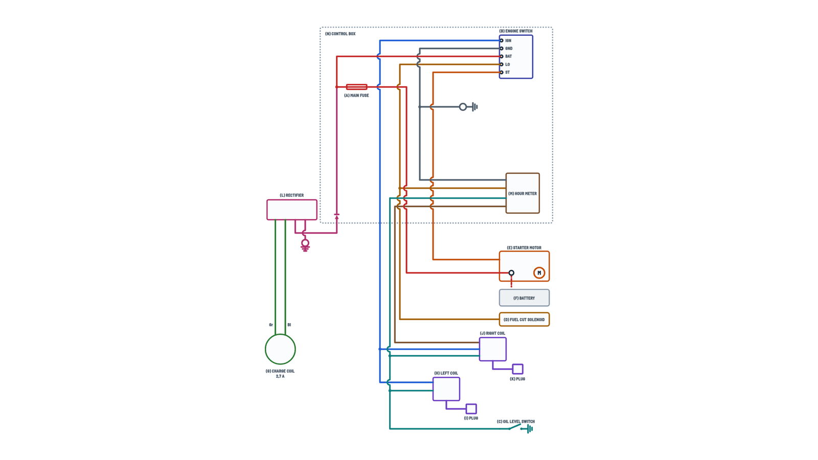
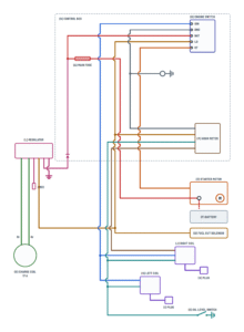
Choose the charge coil and whether the engine has a control box; tap any wire to see what it does.
Terminals and components · 11
- Switch
- Ignition (Bl)
- Battery (W)
- Starter
- LO (Bl/Y)
- Oil (Y)
- Charging
Switch continuity
Position Connects OFF IG to E (ground): engine can't run ON BAT to LO START BAT to LO and ST Wire colors
Code Color Bl Black Y Yellow Bu Blue G Green R Red W White Gr Gray Battery
The battery (F) positive goes to the starter solenoid post and the negative to engine ground.
If the engine won't crank
Check the main fuse and that the battery is charged.
2.7 A rectifier
Gray and black from the charge coil, white output and black to ground.
17 A regulator
Six wires: two grays from the coil, white/blue free, black/yellow to the LO circuit, white output and black to ground.
About This Diagram
This diagram is redrawn from page 18 of the Honda GX690 Engine manual, and we offer it completely free and in English. We have also categorized it in the Generators & Transfer Switches (Home Electrical) section on Diagramverse, and it has been rated by 1 user with an average rating of 5.0. If you have any specific questions about the Honda GX690 Gas Engine Wiring Diagram, we suggest checking the Frequently Asked Questions (FAQs) section.
Printable Honda GX690 Wiring Diagrams
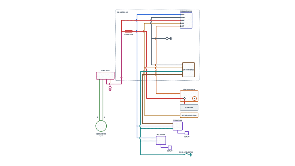
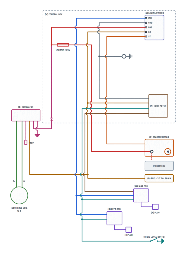
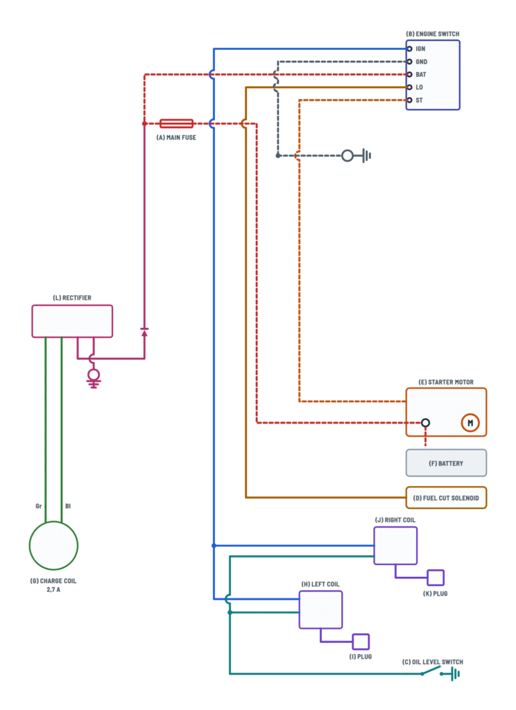
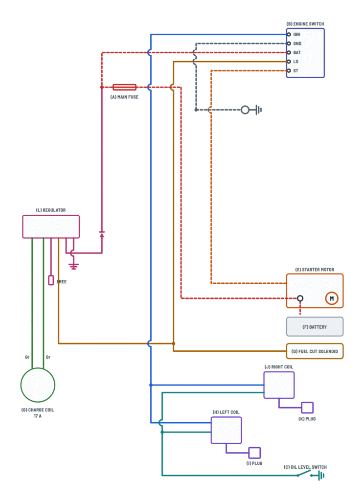



Wiring Instructions
Before you start
First, find out which Honda GX690 wiring variant you have. Look at the leads that run from the Charge coil (G) to the Rectifier or regulator (L). If you see one gray lead and one black lead, you have the 2.7 A charge coil with a rectifier. If you see two gray leads, you have the 17 A charge coil with a regulator, which also has W/Bu, Bl/Y, W and Bl leads. Next, check whether the engine has a control box with an Hour meter (M). If it does, use a "with box" variant. If not, use "no box". The diagram is different for each of the four combinations.
Tools: a socket and wrench set, a 5/8-inch spark plug wrench, a digital multimeter, insulated screwdrivers and battery terminal grease. Materials: a 12 V battery (36 Ah is recommended), a spare 30 A fuse, battery cables, and cable ties or harness bands. The engine documentation gives no cable gauge. Use cables at least as heavy as the ones supplied with your equipment, and keep the starter cables as short as you can, because they carry the full cranking current.
Before you touch any wiring, make it safe:
- Set the Engine switch (B) to OFF.
- Disconnect the battery negative cable.
- Pull both spark plug caps off.
- Let the engine and muffler cool down.
The engine circuit runs on low-voltage 12 V DC. Work on it usually doesn't need an electrical permit, but check your local rules. If the engine drives a generator that feeds a building, a licensed electrician must make that connection. Any repairs inside the ignition or charging system should go to a Honda servicing dealer.
Step-by-step wiring
- Mount the Engine switch (B) and identify its five terminals: IGN, GND, BAT, LO and ST.
- Connect the Green ground wire (GND · G) from GND to a clean, bare-metal engine ground point. On "with box" variants, this wire also goes to the hour meter. Every circuit that follows depends on this ground.
- Connect the Black ignition wire (IGN · Bl) from IGN to both ignition coils, (H) and (J). This is the stop circuit: in OFF, the switch grounds this wire.
- Connect the yellow wire from the Oil level switch (C) to the ignition coils. On "with box" variants, it also goes to the hour meter. Make sure no bare section of this wire touches metal.
- Connect the black/yellow wire from LO to the Fuel cut solenoid (D). On 17 A variants, this wire also feeds the regulator. On "with box" variants, it also feeds the hour meter.
- Connect the black/white wire from ST to the solenoid of the Starter motor (E).
- Connect the gray charge coil leads to the rectifier or regulator exactly as your variant shows, then connect its ground. Route its white output to the fuse node.
- On "with box" variants, finish the hour meter: G to ground, Bl/Y to LO, Y to the oil line, and Bu to the right coil.
- Connect BAT to the Main fuse (A), then connect the white wire from the other side of the fuse to the battery post on the starter. Fit only a 30 A fuse. Put the fuse cover and the switch box rear cover back on.
- Connect the battery:
- Coat the terminals and cable ends with grease.
- Connect the negative cable to an engine mounting bolt, a frame bolt, or another good engine ground.
- Connect the positive cable to the starter solenoid terminal.
- Connect the positive cable to the battery positive terminal.
- Connect the negative cable to the battery negative terminal last.
Never reverse the polarity: that short-circuits the charging system.
- Bundle and secure the harness away from the muffler, the spark plug leads and any moving parts.
Testing and start-up
Do these checks before you connect the battery:
- With the switch in OFF, IGN should show continuity to ground.
- In ON, IGN should be open (no continuity to ground).
- BAT should show no continuity to ground.
Then connect the battery and refit the spark plug caps. Measure at the battery: a fully charged 12 V battery usually reads about 12.6 V at rest (this is general battery practice, not an engine specification).
- Turn the switch to ON. LO should now read close to battery voltage to ground, and the fuel cut solenoid should be energized.
- Turn to START and hold it for no more than 5 seconds. If the engine doesn't start, release the switch and wait at least 10 seconds before trying again.
- Once the engine starts, release the switch. It should spring back to ON.
- With the engine running, battery voltage should rise a little above the resting value. That shows the charging circuit is working.
- On "with box" variants, the hour meter should count only while the engine is running, not with the switch in ON alone.
- Turn the switch to OFF. The engine should stop right away.
Safety notes
- The Ignition coils and spark plugs (H) (J) carry high voltage while the engine runs or cranks. Never touch the spark plug leads, the caps or the coils with the engine turning.
- A battery can explode. Keep sparks and flames away from it, and wash your hands after handling the terminals, because they contain lead.
- Never fit a fuse larger than 30 A. A bigger fuse can lead to serious damage or a fire.
- Don't disconnect the battery while the engine is running. The fuel cut solenoid shuts off fuel and the engine stops.
- Run your tests outdoors only, because the exhaust contains carbon monoxide.
- Keep wiring and your hands away from the hot muffler.
Troubleshooting
| Symptom | Probable Cause | What to Check |
|---|---|---|
| Nothing happens when I turn the key to START, not even a click | The 30 A main fuse has blown, the battery is flat, or the positive cable is loose | Remove the switch box rear cover and inspect the Main fuse (A). Replace it only with a 30 A fuse. Measure from BAT to ground: you should see full battery voltage. Tighten and clean both battery cable ends. |
| The starter clicks or turns slowly but won't crank the engine | The battery is weak, the negative cable has a poor engine ground, or the cable at the starter solenoid is corroded | Measure battery voltage while you crank. If it drops sharply, recharge or replace the battery. Move the negative cable to a clean engine mounting bolt, then clean and grease all terminals. |
| The engine cranks fine but never fires | The Black ignition wire (IGN · Bl) is grounded somewhere, or GND and IGN are swapped at the switch | With the switch in ON, IGN must be open to ground. Disconnect the Bl wire at the switch and try again. If the engine now fires, look for chafed insulation on that wire or a wiring error at the switch. |
| The engine fires briefly, then dies, or runs only with the choke closed | The Fuel cut solenoid (D) isn't getting power: the Bl/Y wire is loose or on the wrong terminal | With the switch in ON, measure from LO to ground at the solenoid connector. It should read close to battery voltage. Check that the Bl/Y wire really comes from LO. |
| The engine stops by itself on rough ground or when someone bumps the battery | A loose battery cable is cutting power to the fuel cut solenoid | Tighten both battery cables and the white wire at the starter post. The engine needs the battery connected to keep running. |
| The engine keeps running when I turn the switch to OFF | The IGN wire is broken, or the switch GND isn't grounded | With the switch in OFF, check continuity from IGN to ground at both coils. You should see continuity. Make sure the green wire is firmly bolted to clean engine metal. |
| The engine shuts down and the red oil light comes on even though the oil is full | The yellow oil level switch wire is chafed against ground, or the oil level switch itself is faulty | Disconnect the yellow wire at the Oil level switch (C) and check it for a short to ground along its whole length. Confirm the oil level on the dipstick before you test anything else. |
| The fuse blows again and again | A short circuit in the white or BAT wiring, the battery connected backward, or an overload | Check the polarity at the battery. Look for wires rubbing on metal near the starter and the regulator. If new fuses keep blowing, have a Honda servicing dealer inspect the charging system. |
| The battery keeps going flat even though the engine runs for hours | A charge coil lead is loose, the rectifier or regulator ground is poor, or the wiring doesn't match your variant | Compare battery voltage with the engine running against the resting value. Running voltage should be higher. On 17 A engines, confirm the regulator's Bl/Y lead is connected to LO, and check the ground of the Rectifier or regulator (L). |
| The starter turns as soon as I switch to ON | The LO and ST wires are swapped at the engine switch | Disconnect the battery. Then make sure black/white goes from ST to the starter solenoid and black/yellow goes from LO to the fuel cut solenoid. |
| The hour meter never counts while the engine runs | The meter's green ground or blue lead to the right coil is loose | Check the G and Bu connections at the Hour meter (M). Keep in mind that the meter doesn't count with the switch in ON alone, only while the engine is running. |