Danfoss TP5000SI Thermostat Wiring Diagram
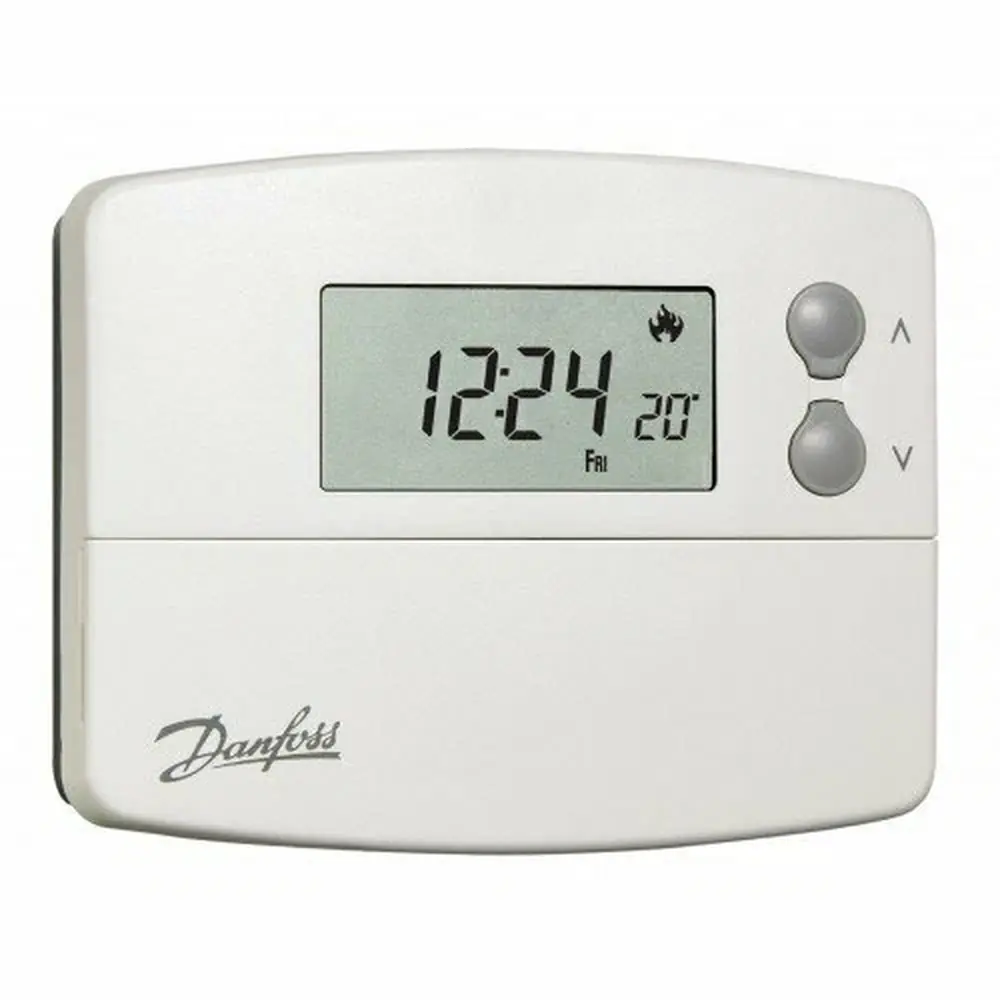
Danfoss TP5000 Si thermostat wiring
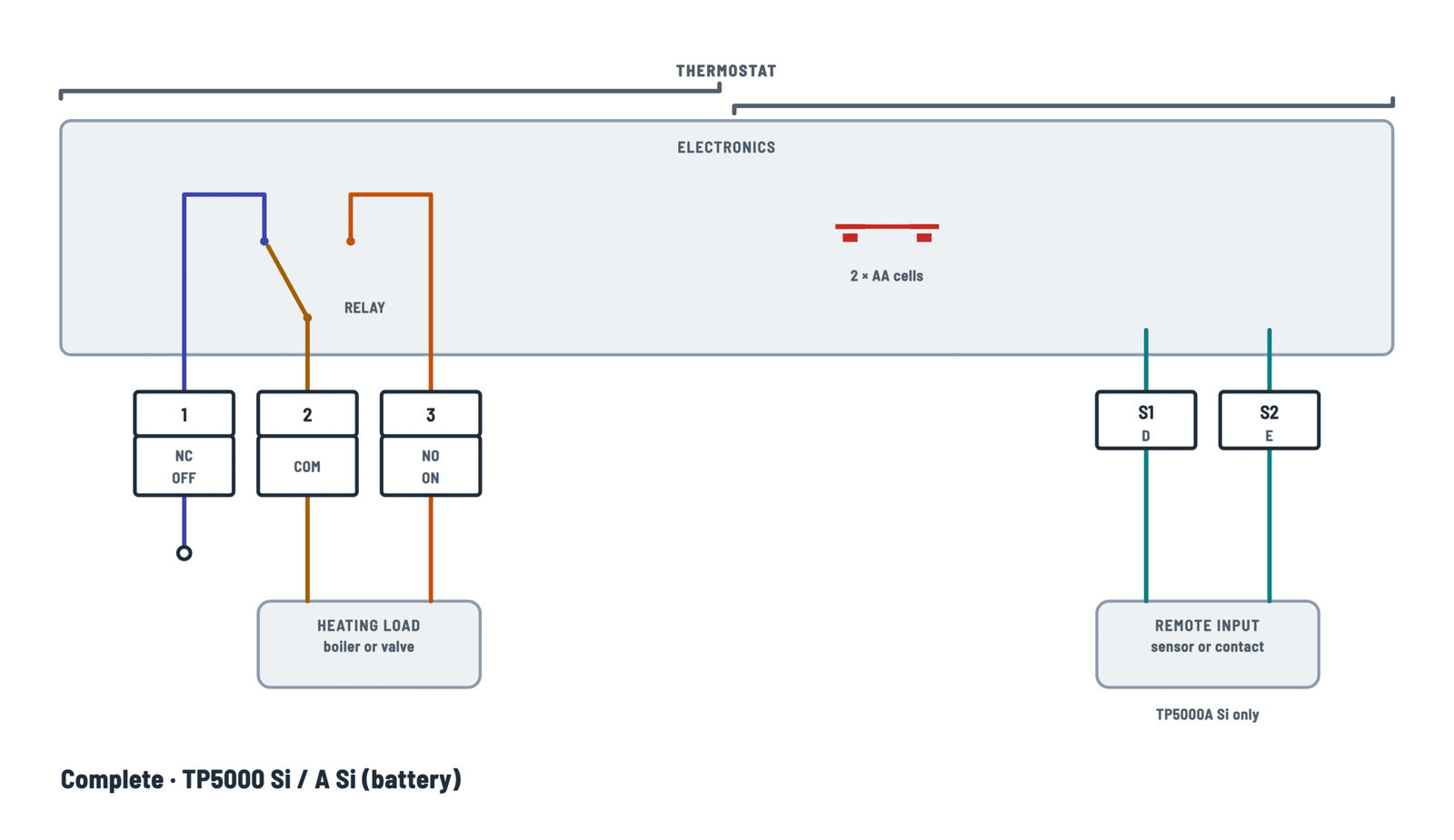
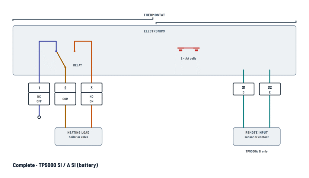
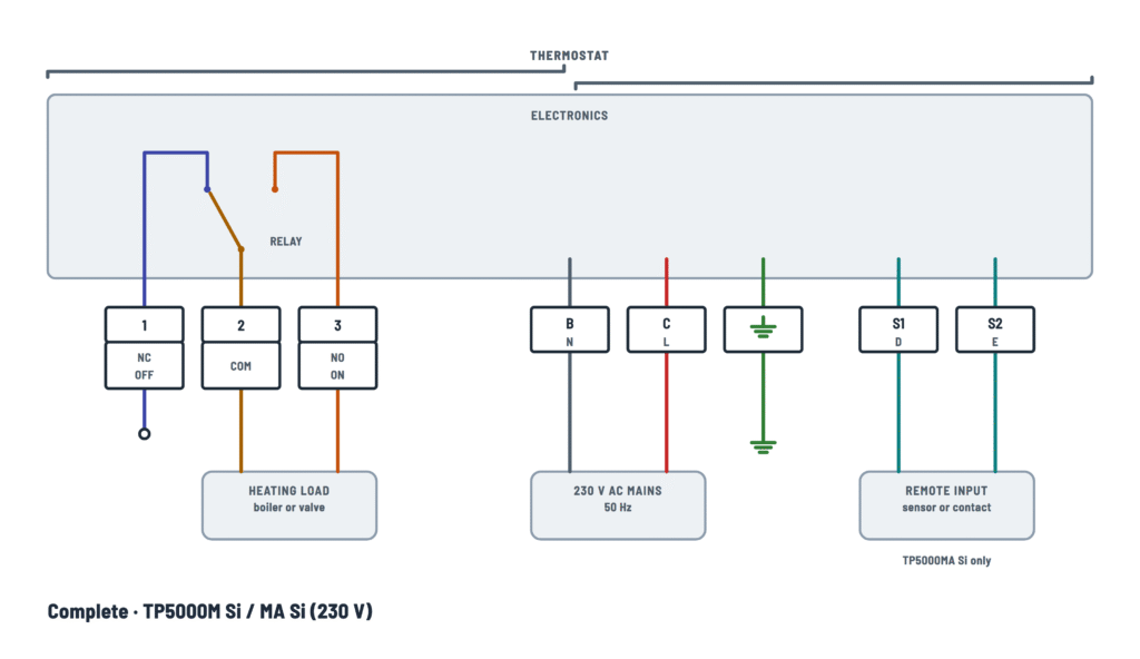
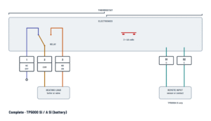
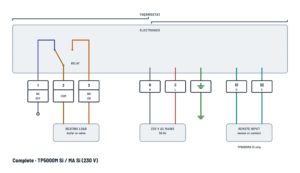
Output relay 1-2-3, power supply (batteries or 230 V) and S1/D-S2/E remote input.
Terminals and components · 5
- COM
- NO / ON
- NC / OFF
- Batteries
- Live
- Neutral
- Earth
- Remote input
Connection
Connect the supply side of the circuit that drives the heating here (for example, the live or the common of the boiler demand). When the thermostat calls for heat, the common joins terminal 3; at rest it stays joined to terminal 1.
Caution
- Installation must be carried out by a qualified electrician or heating installer. Switch off the heating circuit supply before wiring.
- The relay supplies no voltage of its own: the voltage it switches comes from the load circuit.
- Voltage-free changeover (SPDT) relay: 3(1) A, 10 to 230 V.
Connection
This is the usual output: run this terminal to the boiler demand input or to the zone valve. Together with terminal 2 it makes up the heating load connection.
Caution
- Voltage-free changeover (SPDT) relay: 3(1) A, 10 to 230 V.
Connection
Use it only if the equipment needs the reverse action (power while there's no demand). In a normal heating installation it stays free.
Caution
- Voltage-free changeover (SPDT) relay: 3(1) A, 10 to 230 V.
Start-up
Fit the cells with the polarity marked in the compartment, then press and release RESET. The display may stay blank until you do.
Caution
- If the old thermostat had a neutral or earth wire, don't connect them to any TP5000 Si terminal: make them safe and coil them in the recess at the back.
Low battery
After the low battery warning you have 15 days to replace them. If they run out, the relay is parked OFF; the installer can park it ON instead (option 38) to prevent freezing.
Connection
On the 230 V version the supply goes to L and N. The relay is still voltage free: this live doesn't reach terminals 1, 2 and 3 unless you wire it there.
Caution
- Installation must be carried out by a qualified electrician or heating installer. Switch off the heating circuit supply before wiring.
Connection
Run the neutral from the same circuit that feeds terminal L.
Check
The figure shows the earth terminal without stating its use. Connect the supply cable's earth conductor to it if there is one, and check the instructions for the 230 V model.
What connects here
- Remote room sensor (TS2, accessory).
- Limit sensor, for example a floor sensor (accessory).
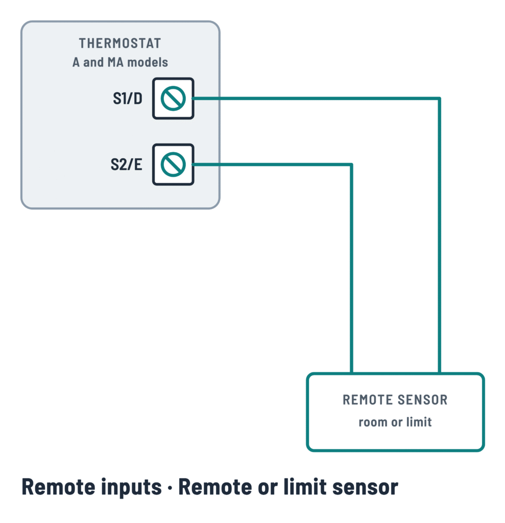
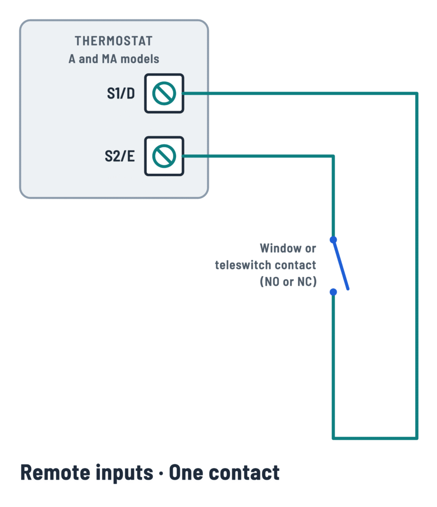
- Window contact, card reader or teleswitch contact.
Tip
The "Remote inputs" tab shows each wiring option and the installer setting that enables it.
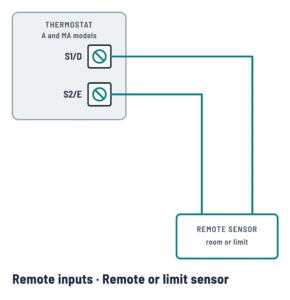
S1/D and S2/E remote input
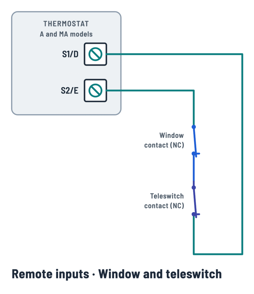
The three ways to use the remote input on A and MA models.
Terminals and components · 2
- Input and sensor
- Contact
- Teleswitch
Connection
The two sensor wires go to S1/D and S2/E.
Installer option 90
Setting Input set up as 0 No remote sensor 1 Room or duct sensor; disables the built-in sensor (factory) 2 Limit (floor) sensor; cut-out point in option 93 3 Digital input: window, card reader or teleswitch; type in option 94 Caution
Connect only sensors or voltage-free contacts: never bring mains voltage to these terminals.
Connection
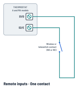
The contact is wired between S1/D and S2/E.
Installer option 90
Setting Input set up as 0 No remote sensor 1 Room or duct sensor; disables the built-in sensor (factory) 2 Limit (floor) sensor; cut-out point in option 93 3 Digital input: window, card reader or teleswitch; type in option 94 Caution
Connect only sensors or voltage-free contacts: never bring mains voltage to these terminals.
Connection
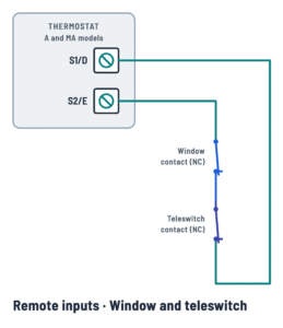
The two NC contacts go in series between S1/D and S2/E: if either opens, the circuit opens.
Installer option 90
Setting Input set up as 0 No remote sensor 1 Room or duct sensor; disables the built-in sensor (factory) 2 Limit (floor) sensor; cut-out point in option 93 3 Digital input: window, card reader or teleswitch; type in option 94 Caution
Connect only sensors or voltage-free contacts: never bring mains voltage to these terminals.
Use
- Room or duct (option 90 = 1): the thermostat measures with the remote sensor instead of the built-in one. Order the TS2 sensor (code 087N681100).
- Limit (option 90 = 2), for example a floor sensor: above the option 93 point (20 to 50 °C, 27 °C from the factory) the output turns off until it drops 2 °C, and "F10" flashes.
Tip
Fit the room sensor about 1.5 m from the floor, away from draughts and heat sources.
Option 94 (option 90 set to 3)
Setting Contact Effect 0 NC Opening the circuit switches to thermostat mode; closing it returns to the program 1 NO Closing the circuit switches to thermostat mode; opening it returns to the program (factory) Operation
In thermostat mode the unit holds the fixed temperature set in user option 10 (5 °C from the factory).
Tip
To override the change at the thermostat, press both temperature arrow buttons together.
Setup
With two contacts in series both must be NC: set option 90 to 3 and option 94 to 0. When either one opens, the unit switches to thermostat mode.
Operation
In thermostat mode the unit holds the fixed temperature set in user option 10 (5 °C from the factory).
Use
A telephone-operated switch, a card reader or a building management system can put the unit into thermostat mode when the building is unoccupied.
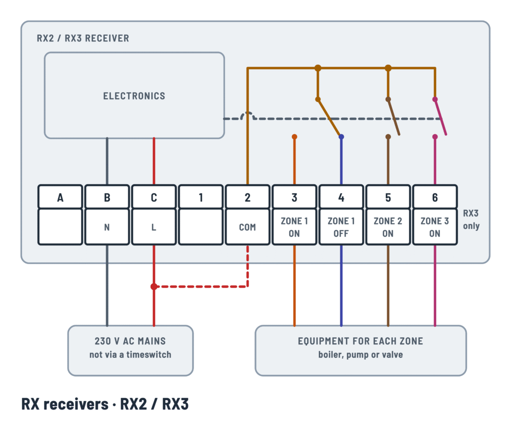
RX receiver wiring (RF models)
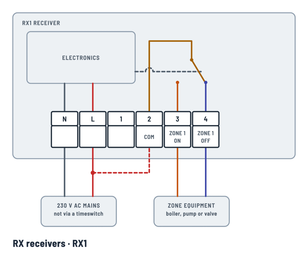
The wireless models drive the boiler through an RX receiver powered at 230 V.
Terminals and components · 7
- Live
- Neutral
- Link (mains systems)
- COM
- Zone 1 ON
- Zone 1 OFF
- Zone 2
- Zone 3
Caution
- The receiver supply must not be switched by a timeswitch: it must be permanently on.
- Installation must be carried out by a qualified electrician or heating installer.
Connection
Run the neutral from the same circuit that feeds terminal L.
When it's needed
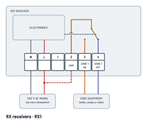
If the boiler, pump or valve is driven at 230 V, link terminal 2 to the live supply so the zone outputs deliver that live. If the boiler demand is a voltage-free or low-voltage contact, leave the link out and take the common of that circuit to terminal 2.
Caution
With the link fitted, terminals 2 to 6 are at 230 V.
Connection
It's the common of the zone 1 changeover contact: it joins terminal 3 on demand and terminal 4 without.
Tip
On mains-voltage systems, this terminal gets the live through the link from L.
Connection
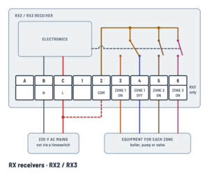
It's the common of every zone: zone 1 (terminals 3 and 4), zone 2 (terminal 5) and, on the RX3, zone 3 (terminal 6).
Tip
On mains-voltage systems, this terminal gets the live through the link from L.
Connection
This is the usual zone 1 output: run it to the boiler demand input, the pump or the zone valve.
Connection
Use it only if some equipment needs the reverse action; otherwise leave it free.
Connection
Run this terminal to the zone 2 valve or equipment. The second thermostat is paired with the receiver's CH2 button.
Connection
Run this terminal to the zone 3 valve or equipment. The third thermostat is paired with the receiver's CH3 button.
Check
No function is given for these terminals: leave them free unless the receiver's instructions say otherwise.
About This Diagram
These diagrams are redrawn from page 4 of the Danfoss TP5000SI Thermostat Data Sheet, and we offer them completely free and in English. We have also categorized it in the Thermostats (HVAC & Water Heating) section on Diagramverse, and it has been rated by 1 user with an average rating of 5.0. If you have any specific questions about the Danfoss TP5000SI Thermostat Wiring Diagram, we suggest checking the Frequently Asked Questions (FAQs) section.
Printable Danfoss TP5000SI Wiring Diagrams
Wiring Instructions
Before you start
First, find out which model you have, because this tells you which diagram view to follow. The Danfoss TP5000SI and TP5000A Si run on two AA alkaline cells and need no mains supply. The TP5000M Si and TP5000MA Si run on 230 V, 50 Hz mains. Models with an "A" in the name have the S1/D · S2/E remote input. The RF models are wireless: the thermostat holds no load wiring, and the load connects to an RX1, RX2 or RX3 receiver instead. Pick the matching variant in the Complete, Remote inputs or RX receivers tab before you begin.
This product should be installed by a qualified electrician or competent heating installer, following your local wiring regulations. Have these ready:
- Small flat and Phillips screwdrivers, wire strippers and a non-contact voltage tester
- A multimeter with continuity and AC voltage ranges
- Two high-quality AA alkaline cells for battery models
- Cable suited to mains voltage for the relay and supply circuits. The sources give no conductor size, so size the cable to the circuit protection and to local code. The relay is rated 3(1) A, 10–230 V, so it is a control-circuit device, not a direct heater switch.
Turn off the circuit that feeds the boiler, valve or heating controls at the breaker or fused spur. Lock it off if you can, and use your tester to confirm the conductors are dead. Many heating circuits are fed from more than one source, so test every conductor in the back box.
Step-by-step wiring
- Remove the wallplate from the back of the unit. Check the mounting position: about 1.5 m above the floor, away from draughts, radiators, open fires and direct sunlight. Measured from the top left corner of the wallplate, leave at least 15 mm clear to the left and right, 30 mm above and 100 mm below. The plug-in module needs that space.
- Set the 8 DIL switches on the rear of the unit before mounting. They select the number of events, 5/2 day or 24 hour, chrono-proportional or on/off control, keyboard lock and reset. Record any changes you make from the factory positions.
- Deal with old neutral and earth wires (battery models). If the old thermostat had a neutral or earth wire, do not connect it to any TP5000 Si terminal. Insulate each one safely and coil it into the recess at the back of the unit.
- Connect the supply (230 V models only). Land the live on C / L and the neutral on B / N, and connect the protective earth to the ⏚ terminal. This supply powers only the thermostat's electronics.
- Wire the relay. Bring the supply for the heating load circuit to 2 · COM. Connect the boiler or valve "call for heat" conductor to 3 · NO, which closes on heat demand. Use 1 · NC only if your equipment needs a signal while there is no demand. The contact is voltage free, so the same relay can switch a low-voltage boiler input or a 230 V valve circuit, as long as you stay within 10–230 V and 3(1) A.
- Wire the remote input (A and MA models). The terminal block sits on the circuit board above the battery compartment. Connect a TS2 remote room sensor or a floor limit sensor across S1/D and S2/E. If you are using one voltage-free contact, connect it across the same pair. For a window contact plus a teleswitch, wire both NC contacts in series across the two terminals.
- Wire the RX receiver (RF models). Give the receiver a permanent 230 V supply that is never switched by a timeswitch. On mains-voltage systems, link terminal 2 (COM) to the live. Then connect zone 1 to terminal 3, zone 2 to 5 (RX2 and RX3) and zone 3 to 6 (RX3 only).
- Dress the cables neatly, check every screw terminal with a light tug, and refit the unit to the wallplate.
Testing and start-up
- On battery models, fit the cells with the polarity marked inside the battery compartment. Then press and release RESET. The display may stay blank until you do this. Press RESET on 230 V models too, before any commissioning or programming.
- Before you restore power, use the multimeter's continuity range to test the relay. Turn the setpoint up to call for heat: 2–3 should read closed and 2–1 open. Turn it down and the readings should swap.
- Restore power. Raise the setpoint and confirm the boiler or valve starts, then lower it and confirm it stops.
- If you fitted a remote input, open Installer Advanced Programming and set option 90:
- 0: no remote sensor
- 1: remote room or duct sensor (the built-in sensor is then disabled)
- 2: limit sensor. Set the limit with option 93 (20–50°C).
- 3: digital input. Use option 94 to choose NC (0) or NO (1).
- To pair an RF model, press RESET on the thermostat, then hold V and + for 3 seconds. On the RX1, hold PROG and CH1 until the green light flashes once. Use CH2 and CH3 for the extra thermostats on an RX2 or RX3. A thermostat and RX1 sold in a combined pack come paired from the factory.
Safety notes
- Even on a battery thermostat, the relay terminals can carry 230 V from the heating circuit. Treat them as live until you have proved them dead.
- Don't exceed the 3(1) A rating: 3 A resistive, 1 A inductive. Switch pumps, large valves or electric heating through a suitably rated contactor or relay.
- The S1/D and S2/E input takes only a sensor or a voltage-free contact. Never connect mains to it.
- In buildings at risk of freezing, set option 38 so the relay is held ON when the batteries run out. Keep the RF thermostat within 30 m of the receiver, with no boiler cases or large metal objects in the line between them.
Troubleshooting
| Symptom | Probable Cause | What to Check |
|---|---|---|
| The display stays blank after I fitted the batteries | Batteries in the wrong way round, or the unit hasn't been reset | Check each cell against the polarity marks in the compartment, fit fresh alkaline cells and press and release RESET. Don't leave batteries in a unit whose display won't come on. |
| The thermostat shows a demand but the boiler never fires | No supply on 2 · COM, or the load is wired to 1 · NC instead of 3 · NO | With power off, measure continuity: 2–3 should close on demand. With power on, confirm the load supply is on COM and that the boiler conductor is on terminal 3. |
| The heating runs when it should be off and stops when it should be on | Load connected to 1 · NC | Move the load conductor from terminal 1 to terminal 3 and test again by raising and lowering the setpoint. |
| A breaker trips or something sparks when I connect the old wires | An old neutral or earth wire landed on a battery-model terminal | Remove the neutral and earth from the TP5000 Si terminals, insulate them and coil them in the rear recess. Only the relay terminals should carry wiring. |
| The 230 V model won't power up | Supply on the wrong terminals or no permanent mains | Measure about 230 V AC between C / L and B / N. Check the spur fuse or breaker and make sure the earth is on the ⏚ terminal, not on N. |
| The room temperature reading is wrong or doesn't change after I fitted a remote sensor | Option 90 doesn't match the sensor, or the sensor wiring is loose | Set option 90 to 1 for a room sensor or 2 for a limit sensor. Retighten both conductors at S1/D and S2/E. |
| The display flashes F10 and the floor heating stops | The limit sensor has reached the option 93 setpoint, or the setpoint is too low | Check the option 93 value (20–50°C). The output comes back once the floor is 2°C below the limit. Check that the sensor is fixed in the right place. |
| The unit stays in thermostat mode even when the window is closed | Option 94 doesn't match the contact type, or the series NC loop is broken | Set option 94 to 0 for NC contacts or 1 for NO. Check continuity across S1/D–S2/E with the window closed and the teleswitch in its normal state. |
| The RF receiver never switches the boiler | No live link to terminal 2, a switched receiver supply, or the thermostat isn't paired | Confirm a permanent 230 V on the receiver's live and neutral terminals, and the link to terminal 2 on mains systems. Repeat pairing until the green light flashes once. |
| Zone 2 or zone 3 doesn't respond on a multi-zone receiver | Load on the wrong terminal, or the thermostat is paired to the wrong channel | Zone 2 is terminal 5 and zone 3 is 6 (RX3 only). Pair each thermostat using PROG with CH2 or CH3. |