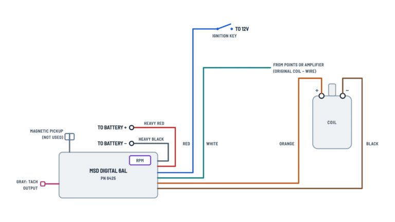
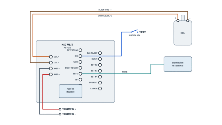
MSD 2 Step 8739 Launch Control Wiring Diagram
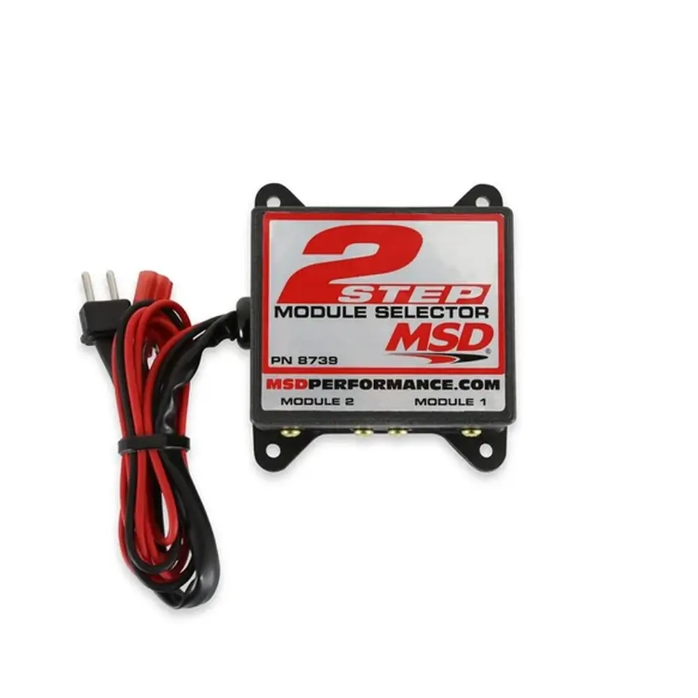
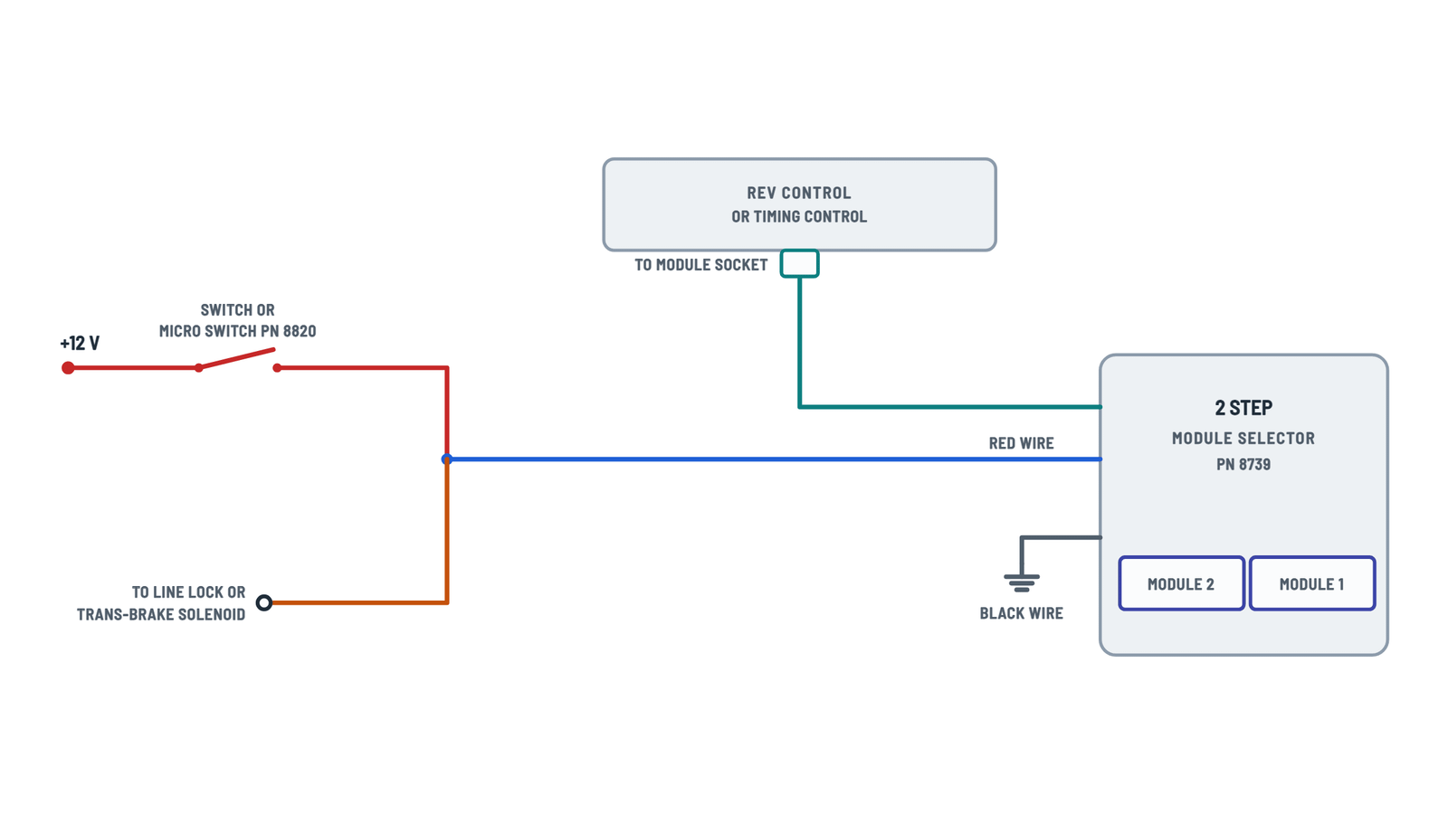
2 Step 8739 connections
Selector connected to the rev control, with a switch or with a latching relay.
Terminals and components · 6
- +12 V
- Activation (red)
- Ground
- Harness
- Modules
- Solenoid
- Relay
Compatibility
Works with a Soft Touch Rev Control or any MSD timing control that uses plug-in modules.
Which module is active
Module When it is active 2 Default, with no voltage on the red wire 1 With 12 V on the red wire Modules
They can be rpm or degree modules, depending on the control the selector is connected to.
Connection
Splice it to the switch output and to the solenoid wire.
Connection
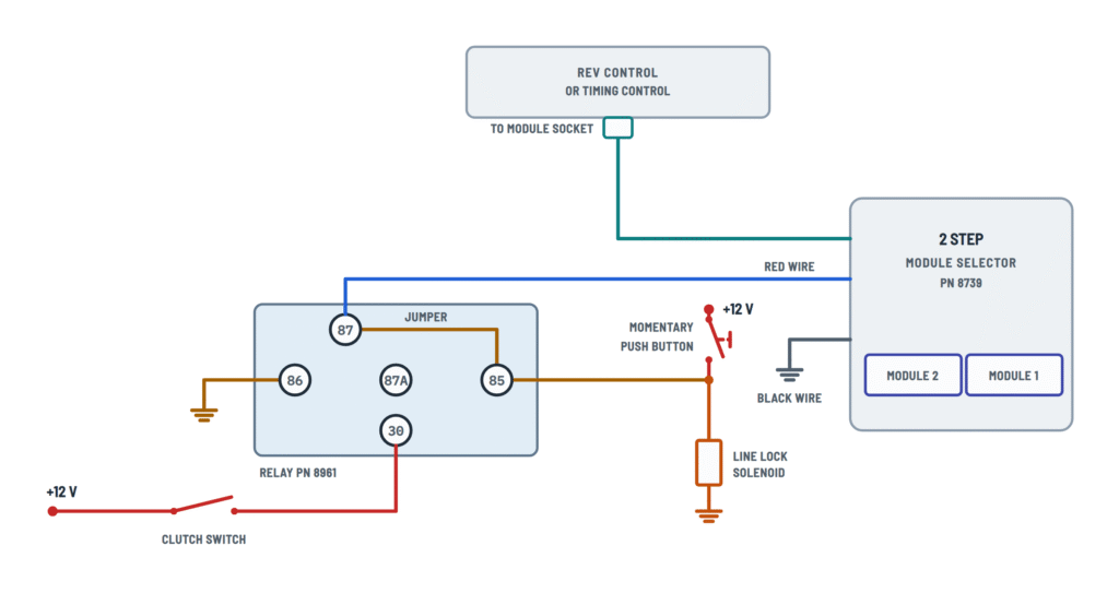
Connect it to relay terminal 87, which is jumpered to terminal 85: it gets 12 V while the relay is latched.
Tip
Use a ring terminal bolted to clean metal.
Options
- A regular switch or the MSD micro switch PN 8820.
- With the switch open, module 2 is active again.
Connection
The solenoid wire is spliced to the red wire and the switch output.
Connection
It connects to the push button output and relay terminal 85; the other end goes to ground.
Terminals
Terminal Goes to 30 Clutch switch (+12 V) 85 Push button, solenoid and jumper from 87 86 Ground 87 Red wire and jumper to 85 87A Unused How it works
- With the clutch pedal down, press the button: the relay pulls in and the 87–85 jumper keeps it latched.
- While latched, module 1 and the line lock are on.
- When the clutch is released, the relay drops out: module 2 is active again and the line lock releases.
What it is for
If you use the clutch for every shift, this gives a rev limit on the launch only and holds the line lock on until the pedal is released.
Function
Releasing the pedal cuts power to the relay and unlatches it.
Use
A single press is enough: then the relay holds itself.
About This Diagram
This diagram is redrawn from pages 1–3 of the MSD 2 Step 8739 Launch Control manual, and we offer it completely free and in English. We have also categorized it in the Ignition (Automotive) section on Diagramverse, and it has been rated by 1 user with an average rating of 5.0. If you have any specific questions about the MSD 2 Step 8739 Launch Control Wiring Diagram, we suggest checking the Frequently Asked Questions (FAQs) section.
Printable MSD 2 Step 8739 Wiring Diagrams


Wiring Instructions
Before you start
The MSD 2 Step 8739 module selector lets you switch between two plug-in rpm or timing modules. It works with an MSD Soft Touch Rev Control or with any MSD Timing Control that takes plug-in modules. Its usual job is launch control: a low rpm limit while you stage and your normal limit once you're moving. Module 2 is the default. Module 1 takes over whenever the Red wire gets 12 V.
First, pick the variant that matches your car:
- Basic: one switch or the Switch or micro switch PN 8820 sends 12 V to the Red wire and the line lock or trans-brake solenoid together. Use this when the launch limit only needs to work while the switch is held closed.
- With 8961 relay: use this if you have a manual transmission and press the clutch for every shift. The Latching relay PN 8961 gives you the launch limit on the launch only and keeps the line lock on until you let the clutch pedal up. Without the latch, every clutch-pedal shift would also drop you onto the launch limit.
Tools and materials: the selector, its 4 mounting screws and the bag of wiring terminals, a crimp tool, a wire stripper, a test light or digital multimeter, heat-shrink tubing, and the two rpm or timing modules you want to use. The sources don't give a wire gauge. For the Red and Black signal wires, regular automotive primary wire is the usual choice. Size the solenoid feed for the current your solenoid draws, and check that the switch or button you use can handle that current. If you add a fuse to the new 12 V feed, which is good practice, size it from the solenoid and wire ratings.
Use stranded spiral-core or other suppression-type spark plug wires. Never use solid core spark plug wires with any MSD component. This is a low-voltage vehicle job, so you don't need a permit. If you're not comfortable working on a race car's ignition or brake hydraulics, have a qualified automotive technician do it.
Step-by-step wiring
- Turn the ignition off and disconnect the negative battery cable.
- Pick a mounting spot away from exhaust heat, moving parts and the coil and plug wires, close enough that the Harness reaches the rev or timing control. Fasten the selector with the supplied screws.
- Take out the plug-in module that is in the rev or timing control now. Plug the Harness selector plug into that module socket, where the module used to go.
- Put your normal rpm or timing module in socket 2. This is the one active with no voltage. Put the launch module, usually the lower rpm, in socket 1.
- Run the Black wire to a clean, bare-metal chassis or engine ground. Crimp on a ring terminal and scrape off paint under it.
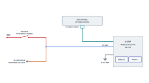
- Basic variant: feed +12 V to the input of the Switch or micro switch PN 8820. Connect the switch output to both the Red wire and the positive side of the Line lock or trans-brake solenoid. Ground the solenoid's other side as its maker specifies.
- With 8961 relay, coil side: connect relay terminal 86 to ground. Install the jumper between 87 and 85.
- With 8961 relay, control side: connect the Clutch switch so it feeds +12 V to terminal 30 only while the clutch pedal is down. Connect the Momentary push button so it sends +12 V to terminal 85, and connect the solenoid's feed to that same circuit.
- With 8961 relay, output side: connect terminal 87 to the Red wire. Connect the solenoid's other end to ground. Leave 87A unused and insulated.
- Crimp every joint, cover it with heat-shrink, and secure the harness with ties away from plug wires and the coil.
Testing and start-up
Reconnect the battery and turn the ignition on, but don't start the engine yet.
- With the switch open, the Red wire should read 0 V to ground. Close the switch, or for the relay variant hold the clutch down and press the button. The Red wire should now read close to battery voltage, and the solenoid should click.
- Relay variant: with the clutch still down, let go of the button. The Red wire should stay at 12 V because the relay is latched. Let the clutch up and it should drop to 0 V. Press the clutch again without touching the button and the Red wire should stay at 0 V.
- Check the Black wire with the meter: resistance to battery negative should be close to zero.
- Start the engine in a safe place with the car secured. Activate the launch circuit and slowly bring the rpm up to the module 1 limit. It should hold there. Release the activation and confirm the engine now limits at the module 2 value. Test at low speed first, then on the track.
Safety notes
- The selector itself runs on 12 V. The ignition system it controls produces very high secondary voltage, so never touch the coil or plug wires while the engine is running.
- A line lock or trans-brake solenoid holds the car with hydraulic pressure. Test it with the car on level ground, wheels chocked, and nobody in front of or behind it.
- Unfused 12 V feeds can start a fire if a wire chafes through. Fuse the feed close to its source and route wires away from sharp edges and exhaust.
- Check that a release or fault always returns to module 2 and turns the solenoid off. Never wire the solenoid so it can stay on with the clutch released.
Troubleshooting
| Symptom | Probable Cause | What to Check |
|---|---|---|
| Engine always hits the launch rpm, even going down the track | Red wire is getting constant 12 V: switch wired to an always-on feed, switch stuck closed, or Red wire shorted to a 12 V circuit | Measure the Red wire to ground with the switch released. It must read 0 V. Look for a stuck switch or chafed insulation, and in the relay variant check that the relay drops out when the clutch is released. |
| Launch limit never works, engine always uses the normal limit | No 12 V reaching the Red wire: dead switch feed, open switch, blown fuse or broken connection | Close the switch and measure the Red wire. It should read close to battery voltage. If it doesn't, trace back through the switch to the 12 V source and check any fuse. |
| The two rpm limits are swapped | Modules installed in the wrong sockets | Put the normal module in socket 2, which is active with no voltage, and the launch module in socket 1, which is active with 12 V on the Red wire. |
| No rev limit at all, or the engine misfires or cuts out at random | Harness plug not fully seated in the module socket, or a missing or loose Black wire ground | Reseat the selector plug firmly in the rev or timing control socket. Measure resistance from the Black wire terminal to battery negative. It should be close to zero, so clean and tighten the ground if it isn't. |
| Rev limit works but the line lock or trans-brake never engages | Solenoid not connected to the switched 12 V, or no ground on its other end | With the launch circuit active, measure voltage at the solenoid feed and check that the solenoid's return goes to a good ground. |
| Relay variant: launch limit and line lock drop out as soon as the push button is released | 87–85 jumper missing, or the clutch switch isn't feeding terminal 30 | Check that the jumper between 87 and 85 is in place. With the clutch down, measure terminal 30. It should read 12 V. |
| Relay variant: the car drops to the launch limit every time the clutch is pressed for a shift | Clutch switch wired to the Red wire or to terminal 85 instead of terminal 30 | Rewire so the Clutch switch feeds only terminal 30 and only terminal 87 feeds the Red wire. |
| Relay variant: line lock stays on after the clutch pedal is released | Clutch switch out of adjustment, or the solenoid fed from a constant 12 V source instead of the latched circuit | With the pedal up, terminal 30 should read 0 V. Adjust or replace the clutch switch, and confirm the solenoid is fed only from the button and 85 circuit. |
| Relay variant: relay clicks but nothing latches, or it never clicks | Terminal 86 not grounded, or wires moved onto 87A | Measure from 86 to ground. It should be close to zero ohms. Move any wire found on 87A to 87, because 87A stays unused. |
| Fuse blows or the switch gets hot when the launch circuit is activated | Solenoid draws more current than the switch, wire or fuse can handle, or the solenoid feed is shorted | Check the solenoid current rating against the switch and fuse ratings. Use heavier wire or switch the solenoid through a relay, and inspect the feed for a short to ground. |