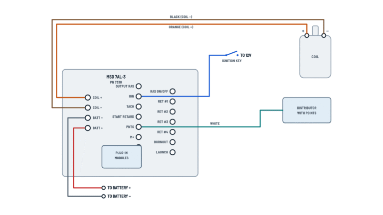
MSD 6AL 6425 Ignition Control Wiring Diagram
Basic installation
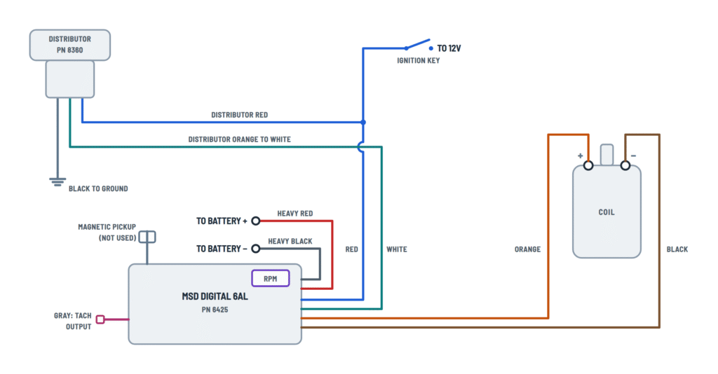
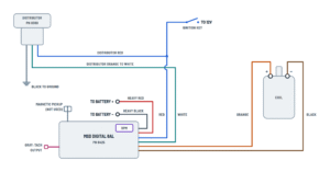
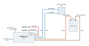
Digital 6AL wiring with points or amplifier trigger, or with an MSD distributor.
Terminals and components · 9
- Battery +
- Ground
- Switched 12 V
- Trigger (white)
- Magnetic pickup
- Coil +
- Coil −
Caution
Never connect it to the alternator. The ignition has an internal fuse: no other fuse is needed.
Good ground
Connect it to clean, paint-free metal and make sure there is a ground strap between the engine and the chassis.
Ballast resistor
It is not needed: if there is one in the coil wiring, bypass it.
Voltage
It must not drop below 10 V while cranking or the ignition will not fire.
Voltage
It must not drop below 10 V while cranking or the ignition will not fire.
Dual points
With dual points, remove the trailing set of points.
One trigger only
Use either the white wire or the magnetic connector, never both.
Not used
With magnetic trigger the white wire is not connected: tape it off.
One trigger only
Use either the white wire or the magnetic connector, never both.
Connection
The connector plugs straight into the MSD distributor or crank trigger with the PN 8860 harness.
Routing
Keep these wires twisted together and away from the other wires and the plug wires.
Danger
This is a capacitive discharge ignition: there is high voltage at the coil terminals. Do not touch them or connect test equipment while cranking or running.
Original wires
Remove the original coil wires: the + wire goes to the MSD red and the − wire to the white (if used).
Tachometers
Some factory tachs need an MSD tach adapter. On GM vehicles with an in-line filter, if the tach drops to zero on acceleration, bypass the filter.
Programmed limit
With a tach on the gray wire, the programmed rev limit is displayed each time the key is turned On.
Setting
- For 10,000 rpm or more, set the left dial to 1 and use the right dial for the hundreds.
- Both dials at zero: no rev limiter.
- It can be adjusted with the engine running.
Cylinder select
Cylinders Wire loops 8 No cut loops 6 Cut one loop 4 Cut both loops LED
It lights with the key On and the engine stopped; when running it flashes with each trigger signal.
Original wire
The wire that fed the original coil + is usually used.
Distributor wires
Wire Goes to Red Switched 12 V, with the MSD red Orange MSD white (trigger) Black Ground Trigger
The 8360 distributor's ignition module still triggers the MSD.
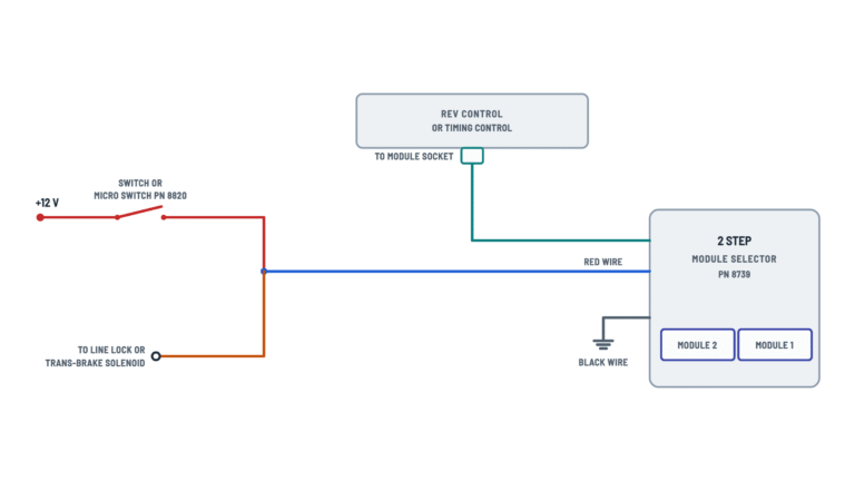
With an MSD control and dual setup
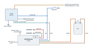
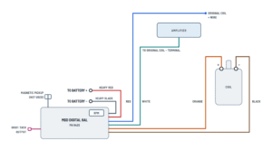
MSD timing control and two ignitions on the same engine.
Terminals and components · 8
- Battery +
- Ground
- Switched 12 V
- Trigger (white)
- Magnetic pickup
- Coil +
- Coil −
Caution
Never connect it to the alternator. The ignition has an internal fuse: no other fuse is needed.
Good ground
Connect it to clean, paint-free metal and make sure there is a ground strap between the engine and the chassis.
Voltage
It must not drop below 10 V while cranking or the ignition will not fire.
One trigger only
Use either the white wire or the magnetic connector, never both.
Routing
Keep these wires twisted together and away from the other wires and the plug wires.
Danger
This is a capacitive discharge ignition: there is high voltage at the coil terminals. Do not touch them or connect test equipment while cranking or running.
Original wires
Remove the original coil wires: the + wire goes to the MSD red and the − wire to the white (if used).
Control wires
Wire Goes to White Points or amplifier (original coil − wire) Yellow MSD white Red Switched 12 V, with the MSD red Black Ground Black and gray High speed retard control Knob
Controls PN 8680, 8762 and 8962 also have a plug-in adjustment knob.
Original wire
The wire that fed the original coil + is usually used.
SPDT switch PN 8807
Sends switched 12 V to the red wire of one MSD or the other: only the selected ignition works.
Automatic selector
Both coil towers go to the automatic coil selector mounted on the distributor.
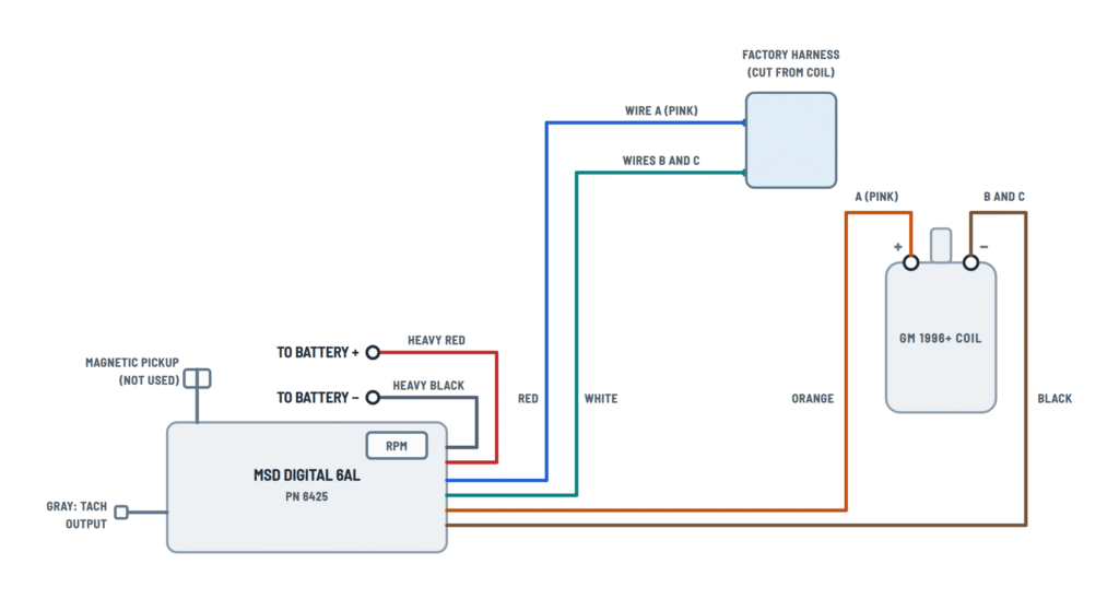
GM ignitions
1996-on GM coil, MSD harness and HEI distributors.
Terminals and components · 7
- Battery +
- Ground
- Switched 12 V
- Trigger (white)
- Magnetic pickup
- Coil +
- Coil −
Caution
Never connect it to the alternator. The ignition has an internal fuse: no other fuse is needed.
Good ground
Connect it to clean, paint-free metal and make sure there is a ground strap between the engine and the chassis.
Voltage
It must not drop below 10 V while cranking or the ignition will not fire.
One trigger only
Use either the white wire or the magnetic connector, never both.
Routing
Keep these wires twisted together and away from the other wires and the plug wires.
Danger
This is a capacitive discharge ignition: there is high voltage at the coil terminals. Do not touch them or connect test equipment while cranking or running.
Original wires
Remove the original coil wires: the + wire goes to the MSD red and the − wire to the white (if used).
A-B-C connector
The coil connector is marked A-B-C: wire A (pink) is positive; the B and C wires are coil negative and their color varies by vehicle.
Plug-in harness
MSD offers a splice-free harness for 1996-on GM vehicles, PN 8877.
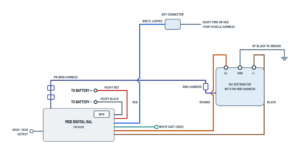
Key connector
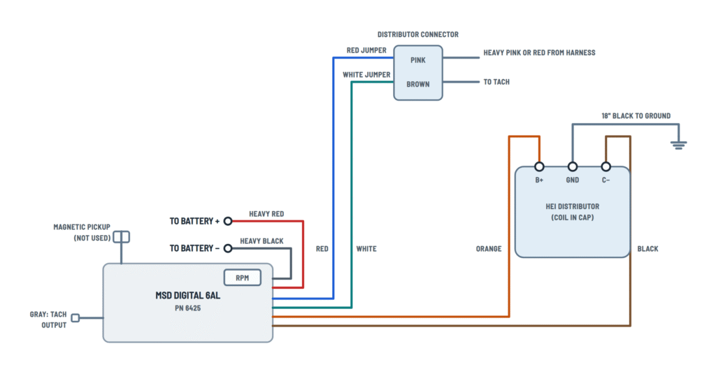
The white jumper joins the MSD red to the key connector, which carries the vehicle's heavy pink or red wire.
Distributor connector
White connects to brown (and the tach) and red to the 12 V pink, using the jumpers supplied with the MSD.
5-pin modules
Some may hesitate or stall on deceleration; MSD offers a diode to correct it.
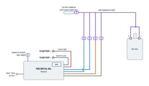
Plug-in harness
It plugs in between the factory harness and the coil: no cutting or splicing. Its red, white, orange and black leads plug into the MSD wires.
Part numbers
- PN 8876: dual connector coil.
- PN 8877: 1996-on GM vehicles.
4-pin module
The GM ignition module is removed and replaced with the MSD PN 8861 harness, which connects the distributor pickup.
Connections
MSD wire Goes to Orange B+ Black C− Pickup 8860 harness → 8861 harness Ground
The 8861 harness wire goes to engine ground.
Connections
MSD wire Goes to Orange B+ Black C− Ground
The 18" black wire goes from the distributor to engine ground.
Ford ignitions
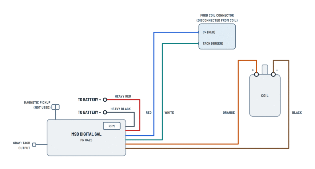
DuraSpark with white wire or magnetic trigger, and TFI coil with harness.
Terminals and components · 7
- Battery +
- Ground
- Switched 12 V
- Trigger (white)
- Magnetic pickup
- Coil +
- Coil −
Caution
Never connect it to the alternator. The ignition has an internal fuse: no other fuse is needed.
Good ground
Connect it to clean, paint-free metal and make sure there is a ground strap between the engine and the chassis.
Voltage
It must not drop below 10 V while cranking or the ignition will not fire.
One trigger only
Use either the white wire or the magnetic connector, never both.
Routing
Keep these wires twisted together and away from the other wires and the plug wires.
Danger
This is a capacitive discharge ignition: there is high voltage at the coil terminals. Do not touch them or connect test equipment while cranking or running.
Original wires
Remove the original coil wires: the + wire goes to the MSD red and the − wire to the white (if used).
Coil connector
Disconnect the original coil connector: its C+ terminal (red) goes to the MSD red and its TACH terminal (green) to the white.
Coil connector
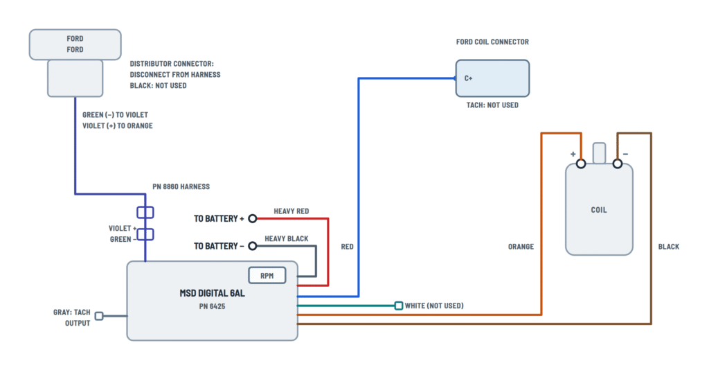
The MSD red goes to the C+ terminal of the original coil connector; the TACH terminal is not used.
Ford pickup
MSD Ford distributor Green (−) Violet Violet (+) Orange — Black: not used Harness
MSD offers the PN 8869 harness to connect the magnetic connector to the DuraSpark connector.
Plug-in harness
It plugs in between the factory Ford harness and the coil, with no cutting. Its red, white, orange and black leads plug into the MSD wires.
With a timing control
It connects as with the GM harness: the white lead goes to the control's white and the control's yellow to the MSD white.
Chrysler ignitions
Chrysler electronic ignition and Dodge with a 2-pin connector.
Terminals and components · 8
- Battery +
- Ground
- Switched 12 V
- Trigger (white)
- Magnetic pickup
- Coil +
- Coil −
Caution
Never connect it to the alternator. The ignition has an internal fuse: no other fuse is needed.
Good ground
Connect it to clean, paint-free metal and make sure there is a ground strap between the engine and the chassis.
Voltage
It must not drop below 10 V while cranking or the ignition will not fire.
One trigger only
Use either the white wire or the magnetic connector, never both.
Routing
Keep these wires twisted together and away from the other wires and the plug wires.
Danger
This is a capacitive discharge ignition: there is high voltage at the coil terminals. Do not touch them or connect test equipment while cranking or running.
Original wires
Remove the original coil wires: the + wire goes to the MSD red and the − wire to the white (if used).
Chrysler pickup
MSD Distributor Green (−) Black (M−) Violet (+) Orange (M+) Original module
The Chrysler ignition module is left disconnected.
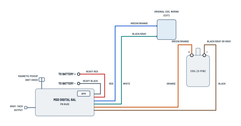
Original wiring
Original wire Goes to Green/orange (from the key) MSD red Black/gray (from the amplifier) MSD white Green/orange on the coil side MSD orange Black/gray or gray on the coil side MSD black Caution
The original coil wiring is cut.
Imports and aftermarket
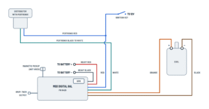
General import wiring, Mallory distributors and Pertronix ignitor.
Terminals and components · 8
- Battery +
- Ground
- Switched 12 V
- Trigger (white)
- Magnetic pickup
- Coil +
- Coil −
Caution
Never connect it to the alternator. The ignition has an internal fuse: no other fuse is needed.
Good ground
Connect it to clean, paint-free metal and make sure there is a ground strap between the engine and the chassis.
Voltage
It must not drop below 10 V while cranking or the ignition will not fire.
One trigger only
Use either the white wire or the magnetic connector, never both.
Routing
Keep these wires twisted together and away from the other wires and the plug wires.
Danger
This is a capacitive discharge ignition: there is high voltage at the coil terminals. Do not touch them or connect test equipment while cranking or running.
Original wires
Remove the original coil wires: the + wire goes to the MSD red and the − wire to the white (if used).
Fuel injected imports
Some will not run or lose the tach with the MSD: they need the PN 8910 adapter (Toyota and Ford Probe, the PN 8910-EIS).
Tachometers
Some factory tachs need an MSD tach adapter. On GM vehicles with an in-line filter, if the tach drops to zero on acceleration, bypass the filter.
Programmed limit
With a tach on the gray wire, the programmed rev limit is displayed each time the key is turned On.
Amplifier
Remove the coil wires: the negative (from the amplifier) goes to the MSD white and the positive to the red.
Mallory pickup
MSD Mallory Green (−) Violet/black Violet (+) Orange/black Unilite wires
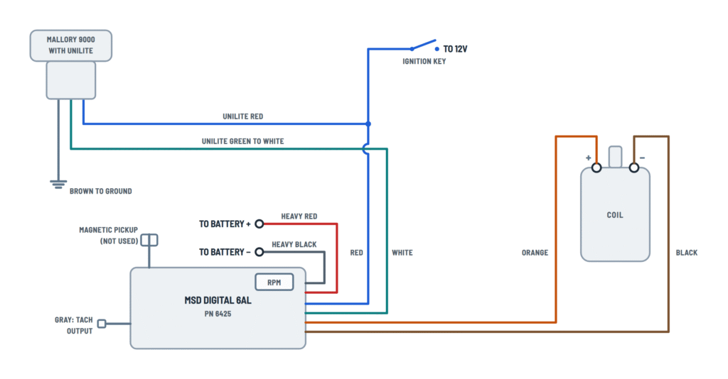
Wire Goes to Red Switched 12 V, with the MSD red Green MSD white Brown Ground Pertronix wires
Wire Goes to Red Switched 12 V, with the MSD red Black MSD white Original wire
The wire that fed the original coil + is usually used.
About This Diagram
These diagrams are redrawn from pages 10–19 of the MSD 6AL 6425 Ignition Control manual, and we offer them completely free and in English. We have also categorized it in the Ignition (Automotive) section on Diagramverse, and it has been rated by 1 user with an average rating of 5.0. If you have any specific questions about the MSD 6AL 6425 Ignition Control Wiring Diagram, we suggest checking the Frequently Asked Questions (FAQs) section.
Printable MSD 6AL 6425 Wiring Diagrams

















Wiring Instructions
Before you start
First, find the tab that matches your vehicle. Use Basic for points, an ignition amplifier, an MSD distributor or crank trigger, or an MSD 8360 distributor. Use MSD controls if you add an MSD timing control or a dual ignition setup. Use GM, Ford or Chrysler for factory ignitions, and Aftermarket for imports, Mallory or Pertronix systems. On GM large cap HEI distributors, remove the cap and rotor and count the terminals on the ignition module. Then pick the 4-pin HEI or the 5 or 7-pin HEI variant.
Next, decide which trigger you will use. The MSD 6AL 6425 has two trigger circuits: the White wire for points, an amplifier or an MSD control, and the Magnetic pickup connector (Violet + and Green −) for a magnetic pickup. Only one is used at a time.
You will need:
- Basic hand tools, a drill with a 3/16" bit and a digital multimeter.
- Soldering equipment and heat-shrink tubing. Every connection must be soldered and sealed.
- Extension wire if needed: 12 gauge for the power leads and 16 gauge for the other wires. You can shorten any wire.
- Quality helically wound spark plug wires. A new distributor cap and rotor are recommended.
The unit needs a negative ground 12 volt system with a distributor. Turn the key off and disconnect the battery, negative cable first. If you are not comfortable working on ignition wiring, have a qualified automotive technician do the job.
Step-by-step wiring
- Set the cylinder count first. The unit comes set for 8 cylinders. For an even-fire 6-cylinder, cut one wire loop on the side of the unit. For a 4-cylinder, cut both loops.
- Choose a mounting spot away from direct engine heat. Avoid enclosed spaces such as the glove box. Check that every wire reaches its connection and that you can get to the rev limiter dials. Mark the holes, drill them with the 3/16" bit and mount the unit on the vibration mounts.
- Remove the original wires from the coil terminals. In most installations, the original coil + wire (from the key) goes to the MSD Red. The original coil − wire (from the points or amplifier) goes to the MSD White. If there is a ballast resistor in the coil wiring, bypass it.
- Connect the Orange wire to coil + and the Black wire to coil −. Nothing else may touch either coil terminal.
- Connect your trigger. With the White wire, tape over the unused magnetic pickup connector. With a magnetic pickup, plug the Violet and Green connector into the MSD distributor, crank trigger or adapter harness shown in your variant, and leave the White wire unused. On a dual point setup, remove the trailing set of points.
- If the Red: switched 12 V wire does not reuse the original coil + wire, connect it to a 12 V source that is live only with the key on.
- Run the Heavy red lead straight to the battery + terminal or the + side of the starter solenoid. Never connect it to the alternator. Run the Heavy black lead to the battery − terminal or to clean, paint-free metal on the engine. Make sure there is a ground strap between the engine and the chassis.
- Connect the Gray: tach output wire to the tachometer trigger wire or another rpm-activated accessory.
- Set the Rev limiter dials under the black cover. The left dial sets thousands and the right dial sets hundreds. For 10,000 rpm and up, put the left dial on 1. Both dials on zero turns the limiter off. If an MSD Ready-to-Run distributor has its own rev limiter, set that one to zero.
- Route the trigger wires away from the other wires and the plug wires, ideally along the block or firewall. Twist the magnetic pickup wires together. Keep all wiring away from headers and sharp edges.
- Reconnect the battery, negative cable last.
Testing and start-up
Before cranking, run through this checklist:
- Only Orange and Black are on the coil terminals.
- The small Red goes to switched 12 V.
- The heavy leads go directly to the battery.
- The engine has a ground strap.
- The cylinder loops are set correctly.
Turn the key on without cranking. The LED should light steadily, and the small Red should read about 12 V to ground. The coil + terminal reads no voltage with the key on; that is normal for this ignition. If a tachometer is on the Gray wire, it briefly shows the rev limit setting each time you turn the key on.
To check for spark without the engine running:
- Turn the key off, pull the coil wire from the cap and hold its end about 1/2" from ground.
- Disconnect the trigger from the distributor and turn the key on.
- With a White trigger, tap the White wire to ground several times. With a magnetic trigger, short Green to Violet with a jumper several times.
- Each time you break the contact, a spark should jump to ground.
Then reconnect the trigger and start the engine. While it runs, the LED flashes with each trigger signal, which looks almost steady at higher rpm. Set the timing with a standard inductive timing light.
Safety notes
- This is a capacitive discharge ignition. Its capacitor charges to roughly 520 to 535 volts, and the coil produces very high voltage. Never touch the coil terminals and never connect test equipment to them while cranking or running.
- Do not use solid core spark plug wires. Do not use digital or dial back timing lights.
- Before welding on the vehicle, disconnect both heavy power leads and the tach ground wire.
- The unit has reverse polarity protection, but still check polarity before you reconnect the battery.
- No inline fuse size is specified for the heavy leads. Keep them short, protect them from chafing and secure every terminal tightly.
Troubleshooting
| Symptom | Probable Cause | What to Check |
|---|---|---|
| Engine cranks but there is no spark and the LED stays off with the key on | The small Red is not getting switched 12 V | With the key on, measure the small Red to ground. You should see 12 V. If not, move it to another switched 12 V source. |
| Engine cranks but won't start, the LED is on, but it never flashes while cranking | Trigger not connected, or the wrong trigger circuit is in use | Use only one trigger: White for points or an amplifier, or Violet and Green for a magnetic pickup. Do the spark test by tapping White to ground or shorting Green to Violet. |
| No spark even though the unit has power and the trigger tests fine | Bad coil, or extra wires on the coil terminals | Make sure only Orange is on coil + and only Black is on coil −. Swap in another coil and repeat the spark test. |
| Misfires, weak running or intermittent cutting out | Poor ground or loose heavy power leads | Check that the Heavy black is on clean, bare metal or battery −, that the engine has a ground strap, and that the Heavy red goes directly to battery + or the starter solenoid, not the alternator. |
| Engine runs badly or fires erratically on a 4 or 6-cylinder | Cylinder select loops not cut | Cut one loop for an even-fire 6, two loops for a 4. Uncut loops mean the unit is still set for 8 cylinders. |
| Engine keeps running after you turn the key off | Charging lamp circuit is back-feeding voltage into the small Red | Install the supplied diode inline in the charging indicator wire, facing the correct direction. On Ford it goes on terminal 1, on early GM terminal 4, and on 1973-1983 Delcotron alternators on the smallest wire leaving the alternator. |
| Tachometer reads zero or jumps around | Tach is not compatible with the trigger, or a GM inline filter is in the circuit | Connect the tach trigger to the Gray wire first. If it still fails, use a PN 8910 adapter with a White wire trigger or a PN 8920 with a magnetic trigger. On GM, bypass the inline filter. |
| Engine stops climbing at a certain rpm, earlier than expected | Rev limiter dials set too low | Under the black cover, the left dial is thousands and the right dial is hundreds. Both on zero turns the limiter off. If you have an MSD Ready-to-Run distributor with its own limiter, set that one to zero too. |
| Imported fuel-injected car won't run after the install | The shared trigger signal is too weak for the fuel injection | Install an MSD Tach Adapter PN 8910. Use PN 8910-EIS if that doesn't fix it, and always on Toyotas and Ford Probes. |
| GM 5-pin HEI hesitates or stalls when you lift off the throttle | Known issue on some 5-pin modules | Contact MSD technical support for the required bolt-in diode. |
| Erratic timing or false triggering with a magnetic pickup | Pickup wires picking up interference, or polarity reversed | Make sure Violet goes to pickup + and Green to pickup −. Twist the two wires together, route them away from the plug wires, and check that the plug wires are not solid core. |
| Engine misses at high rpm when running without an alternator | Battery voltage sags under load | Check battery voltage under load: below 9 V, the output drops. Allow at least 15 amp/hour for every half hour of running, and keep the battery fully charged with clean terminals. |