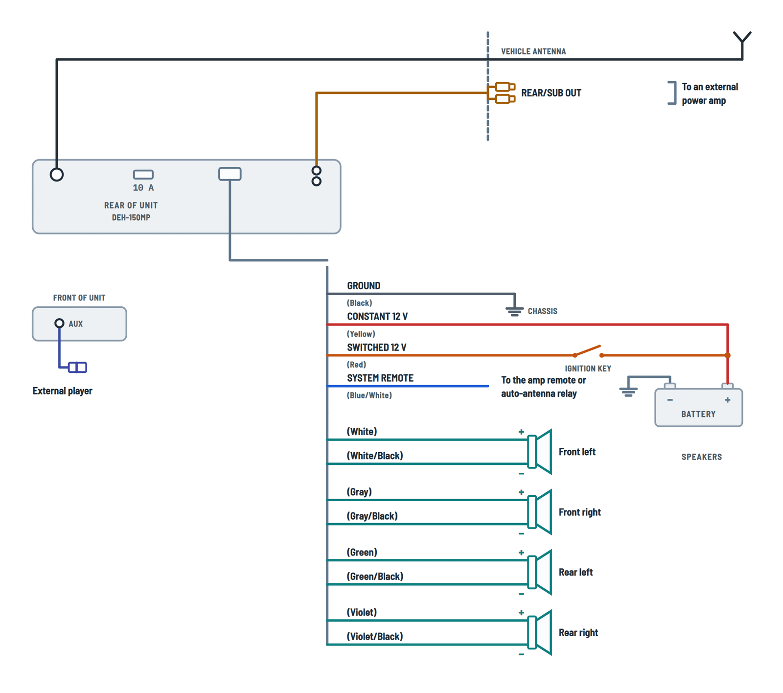
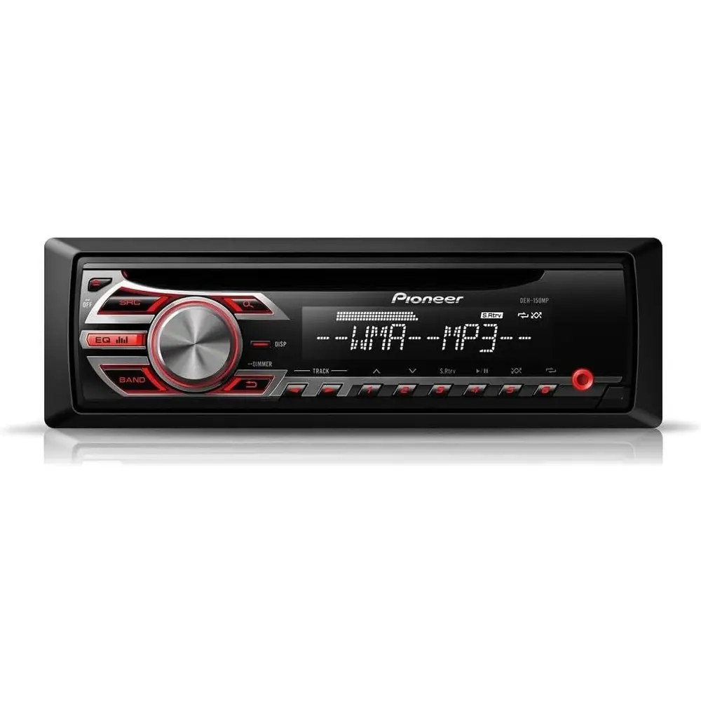
Pioneer DEH-150MP Audio Receiver Wiring Diagram
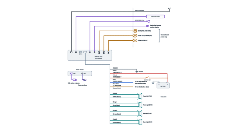
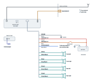
Complete diagram
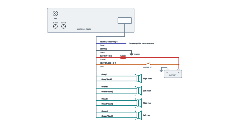
Every cable and connector on the unit and where each one goes.
Terminals and components · 11
- Constant 12 V
- Switched 12 V
- Ground
- System remote
- Illumination and preamp
- Speakers
- AUX input
- Antenna and devices
Settings
Turn the AUX setting on in the menu to use it.
Separate screws
The power amp ground and this unit's ground go to the body with different screws. A loose screw can cause smoke, fire or malfunction.
Caution
Do not run it to the battery through the hole into the engine compartment.
Fuse
The rear of the unit has a 10 A fuse: replace it only with one of the same rating.
No ACC position
If the ignition switch has no ACC position, connect it to a terminal that detects the key; otherwise the battery will drain.
Never to a power terminal
Never connect it to the power terminal of an amp or auto antenna: it may drain the battery or cause a malfunction.
Glass antenna
If the vehicle has a glass antenna, connect it to the antenna booster power supply terminal.
Caution
Tape any unused speaker leads. With a two-speaker system, do not connect anything to the spare leads.
Negative leads
Do not ground the speaker negative lead or band it together with other speakers' negatives.
Caution
Tape any unused speaker leads. With a two-speaker system, do not connect anything to the spare leads.
Negative leads
Do not ground the speaker negative lead or band it together with other speakers' negatives.
Caution
Tape any unused speaker leads. With a two-speaker system, do not connect anything to the spare leads.
Negative leads
Do not ground the speaker negative lead or band it together with other speakers' negatives.
Caution
Tape any unused speaker leads. With a two-speaker system, do not connect anything to the spare leads.
Negative leads
Do not ground the speaker negative lead or band it together with other speakers' negatives.
Plugs
L = left, R = right; connect with RCA cables (sold separately).
Subwoofer
The subwoofer output is monaural.
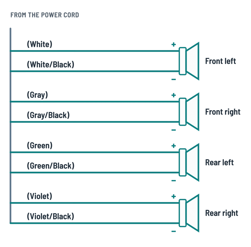
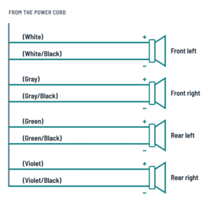
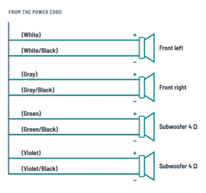
Speaker leads
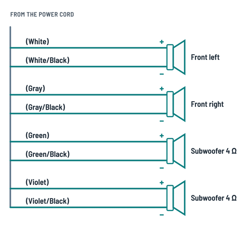
The eight speaker leads with their polarity, with four speakers or with a subwoofer on the rear leads.
Terminals and components · 4
- Speakers
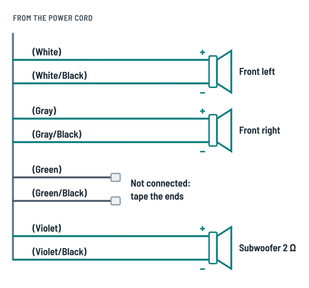
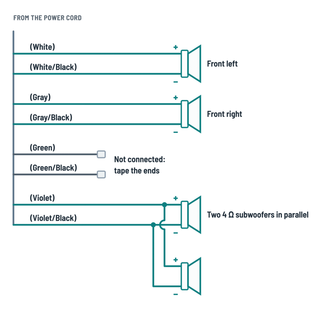
- Unused
Caution
Tape any unused speaker leads. With a two-speaker system, do not connect anything to the spare leads.
Negative leads
Do not ground the speaker negative lead or band it together with other speakers' negatives.
Caution
Tape any unused speaker leads. With a two-speaker system, do not connect anything to the spare leads.
Negative leads
Do not ground the speaker negative lead or band it together with other speakers' negatives.
Caution
Tape any unused speaker leads. With a two-speaker system, do not connect anything to the spare leads.
Negative leads
Do not ground the speaker negative lead or band it together with other speakers' negatives.
Caution
Tape any unused speaker leads. With a two-speaker system, do not connect anything to the spare leads.
Negative leads
Do not ground the speaker negative lead or band it together with other speakers' negatives.
Setting
With a subwoofer on the rear leads, set the rear output to subwoofer (SW) in the menu.
Negative leads
Do not ground the speaker negative lead or band it together with other speakers' negatives.
Setting
With a subwoofer on the rear leads, set the rear output to subwoofer (SW) in the menu.
Negative leads
Do not ground the speaker negative lead or band it together with other speakers' negatives.
2 Ω subwoofer
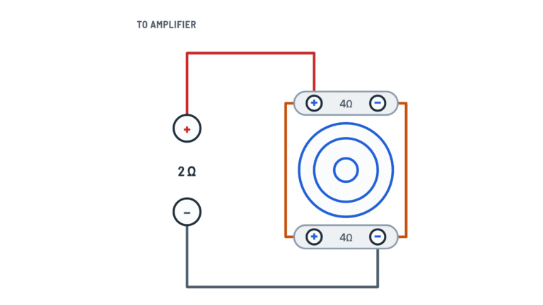
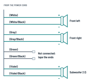
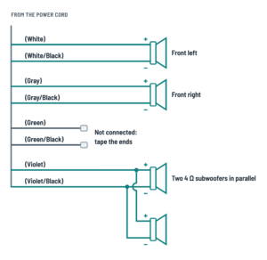
A 2 Ω subwoofer (or two 4 Ω subwoofers in parallel) goes only to the violet and violet/black leads and must be rated over 70 W. Connect nothing to the green and green/black leads.
Setting
With a subwoofer on the rear leads, set the rear output to subwoofer (SW) in the menu.
2 Ω subwoofer
A 2 Ω subwoofer (or two 4 Ω subwoofers in parallel) goes only to the violet and violet/black leads and must be rated over 70 W. Connect nothing to the green and green/black leads.
Setting
With a subwoofer on the rear leads, set the rear output to subwoofer (SW) in the menu.
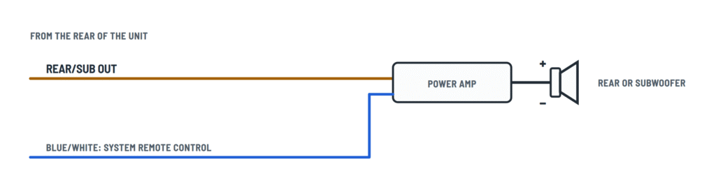
External power amp
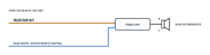
RCA outputs to the amplifiers and the lead that turns them on.
Terminals and components · 3
- Preamp
- System remote
- Amplifier
Amp turn-on
Connect it to the system remote terminal of each amplifier.
Plugs
L = left, R = right; connect with RCA cables (sold separately).
Subwoofer
The subwoofer output is monaural.
About This Diagram
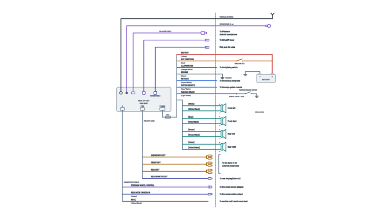
These diagrams are redrawn from pages 9–10 of the Pioneer DEH-150MP Audio Receiver manual, and we offer them completely free and in English. We have also categorized it in the Car Audio & Stereo (Automotive) section on Diagramverse, and it has been rated by 1 user with an average rating of 5.0. If you have any specific questions about the Pioneer DEH-150MP Audio Receiver Wiring Diagram, we suggest checking the Frequently Asked Questions (FAQs) section.
Printable Pioneer DEH-150MP Wiring Diagrams
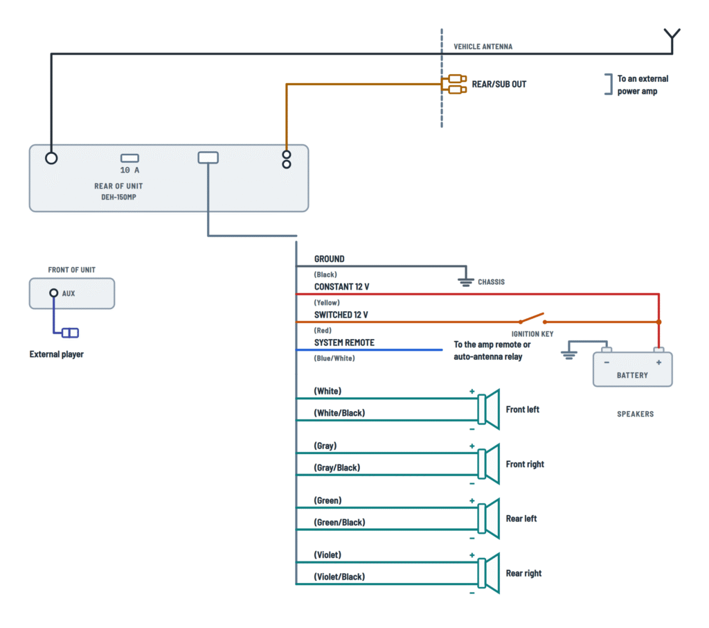
Wiring Instructions
Before you start
The Pioneer DEH-150MP is built for 12 V negative ground vehicles only. Before buying parts, confirm that your vehicle has a 12-volt battery with the negative post bonded to the body. Then decide which tab of the diagram matches your system:
- Complete: four speakers on the built-in amplifier, with an optional amp on the RCA output.
- Speakers: pick the variant that matches your speaker leads. Four speakers is a normal front and rear setup. 4 Ω subwoofers puts a 4 Ω subwoofer on the green leads and another on the violet leads. 2 Ω subwoofer uses the violet leads only. Two 4 Ω in parallel puts two 4 Ω subwoofers on the violet leads as one 2 Ω load.
- Power amp: one or more external amplifiers fed from the Rear or subwoofer output (RCA) and turned on by the Blue/white: system remote lead.
Tools and materials: wire strippers, a crimp tool with insulated butt connectors (or a vehicle-specific harness adapter), a digital multimeter, electrical tape, cable ties or clamps, and screwdrivers or sockets for the dash. Use only speakers rated over 50 W with an impedance of 4 to 8 Ω. Never use 1 to 3 Ω speakers on the four speaker channels.
The unit comes with its own pigtail, and the fuse on the unit is rated 10 A. Do not shorten the factory leads. If you have to extend a lead, use wire at least as thick as the lead you are extending. Your harness adapter or amplifier instructions will give the right gauge for those runs. You don't need a permit or a licensed electrician for this low-voltage work. Have your dealer or an installer do the job if it means drilling holes or modifying the vehicle.
Write down your radio presets, then disconnect the battery negative terminal. Disconnecting the battery erases the unit's preset memory.
Step-by-step wiring
- Find the vehicle wires with a multimeter while the battery is still connected. Then disconnect it. The constant feed reads about 12 V with the key off. The switched feed reads 12 V only with the key in ACC or ON. Label both wires.
- Connect Black: chassis ground first. Run it to a clean, paint-free metal spot on the body and fasten it with its own screw. Any amplifier or other device needs its own separate ground screw. A ground screw that loosens can cause smoke, fire or malfunction.
- Connect Yellow: constant 12 V to the constant supply. Do not run the yellow lead through the firewall to the battery.
- Connect Red: switched 12 V to the ignition-controlled supply. If your ignition switch has no ACC position, connect red to a terminal that follows the ignition key. Otherwise the unit can drain the battery.
- Connect the speaker pairs and keep the polarity right: FL white and white/black, FR gray and gray/black, RL green and green/black, RR violet and violet/black. The plain color is always +.
- For a subwoofer on the speaker leads, follow the Speakers variant you chose. With a single 2 Ω subwoofer or two 4 Ω subwoofers in parallel, use only violet and violet/black. Tape the green and green/black leads separately.
- Never connect any speaker negative lead to the chassis, and never join the negative leads of different speakers together.
- If you add an amplifier, run RCA cables from the Rear or subwoofer output (RCA) to the amp's inputs. Connect Blue/white: system remote to the amp's remote terminal. It can supply up to 300 mA at 12 V DC. You can also use it for an auto-antenna relay control terminal, or for the antenna booster power terminal if the vehicle has a glass antenna. Never connect it to the power terminal of an amplifier or a power antenna.
- Plug the vehicle antenna into the Antenna input.
- Insulate every unused lead separately with tape. This includes unused speaker pairs in a two-speaker system. Do not cut into the unit's power cable insulation to feed other devices, because its current capacity is limited.
- Tie the wiring down and wrap tape wherever it touches metal. Keep it away from seat rails, the shift lever and heater outlets. Leave about 5 cm of clear space behind the unit for cooling, and mount it at less than 60° from horizontal.
Testing and start-up
Do this before you push the unit fully into the dash.
- Reconnect the battery negative. With the key off, yellow should read about 12 V and red should read 0 V. With the key in ACC or ON, both should read 12 V. The unit runs on 10.8 V to 15.1 V.
- Turn the ignition to ON. SET UP should appear on the display, which shows the power feeds are working.
- Go to the initial menu and set SP-P/O MODE for your system. Use REAR/SUB.W for rear speakers plus a subwoofer on the RCA output. Use SUB.W/SUB.W for a subwoofer on the rear speaker leads. Use REAR/REAR when the RCA output feeds rear speakers.
- At low volume, use BALANCE and FADER to check that each speaker plays from the right position. With an amplifier, confirm the amp turns on with the unit and turns off when you switch the unit off.
- To use the AUX input (3.5 mm jack), turn AUX on in the system menu first. Then select it with SRC/OFF.
Safety notes
A 12 V system won't shock you, but a short to the chassis can melt wiring and start a fire. That is why the battery has to be disconnected and the ground has to go on first. Replace a blown fuse only with one of the prescribed rating, 10 A on the unit. Keep liquids away from the unit, and park the vehicle before removing the front panel. Check all connections before final installation.
Troubleshooting
| Symptom | Probable Cause | What to Check |
|---|---|---|
| Unit does not turn on at all | Missing ground, no power on yellow or red, or a blown fuse | Check the 10 A fuse on the unit. Measure yellow to chassis: about 12 V. Measure red with the key in ACC or ON: about 12 V. Confirm the black lead is screwed to bare metal. |
| Radio presets and clock are lost every time I turn off the car | Yellow and red are reversed, or both are on a switched feed | With the key off, yellow must still read about 12 V. If not, move yellow to a constant 12 V source. |
| Car battery goes dead overnight | Red is on a constant feed, which is common on vehicles without an ACC position, or blue/white is driving an amp's power terminal | Key off, red must read 0 V. Make sure blue/white goes only to the amp's remote terminal, never to its power terminal. |
| AMP ERROR appears on the display | A speaker lead is shorted to the chassis, negatives are joined together, or the load is too low | Check each speaker pair for shorts to metal and to the other channels. Confirm no speaker below 4 Ω is on any channel, apart from the 2 Ω subwoofer on violet. Cycle the ignition. |
| Weak, thin bass, or sound seems to come from nowhere | One speaker is wired out of phase, with + and − swapped | Check that the plain-color lead goes to + and the black-striped lead goes to − on every speaker. |
| No sound from the subwoofer on the speaker leads | SP-P/O MODE is still set for rear speakers, or SUB.W is OFF | Set SP-P/O MODE to SUB.W/SUB.W and set SUB.W to NOR or REV in the audio menu. |
| 2 Ω subwoofer cuts out or the unit goes into protection | The subwoofer is on the green leads instead of violet | Move the 2 Ω subwoofer, or the parallel pair, to violet and violet/black, and tape off green and green/black. |
| External amplifier never turns on | Blue/white is not connected, or the amp's ground or power is missing | With the unit on, measure about 12 V on blue/white at the amp's remote terminal. Check the amp's own ground screw and power fuse. |
| Amplifier powers up but plays nothing, or plays the wrong signal | RCA cables are not seated, or SP-P/O MODE does not match the amp's job | Reseat the RCA plugs. Choose REAR/REAR for a rear-speaker amp or REAR/SUB.W for a subwoofer amp. |
| Whine or noise that changes with engine speed | Poor or shared ground | Clean the ground spot down to bare metal and tighten it. Give the head unit and the amp separate ground screws. |
| Weak radio reception or none at all | Antenna plug is not fully seated, or a powered antenna gets no turn-on signal | Push the plug fully into the antenna input. Confirm blue/white reaches the auto-antenna relay or the glass antenna booster terminal. |
| AUX cannot be selected | The AUX setting is off | Turn AUX on in the system menu, then press SRC/OFF to select AUX. |