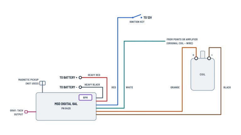
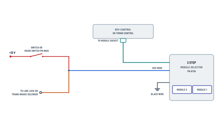
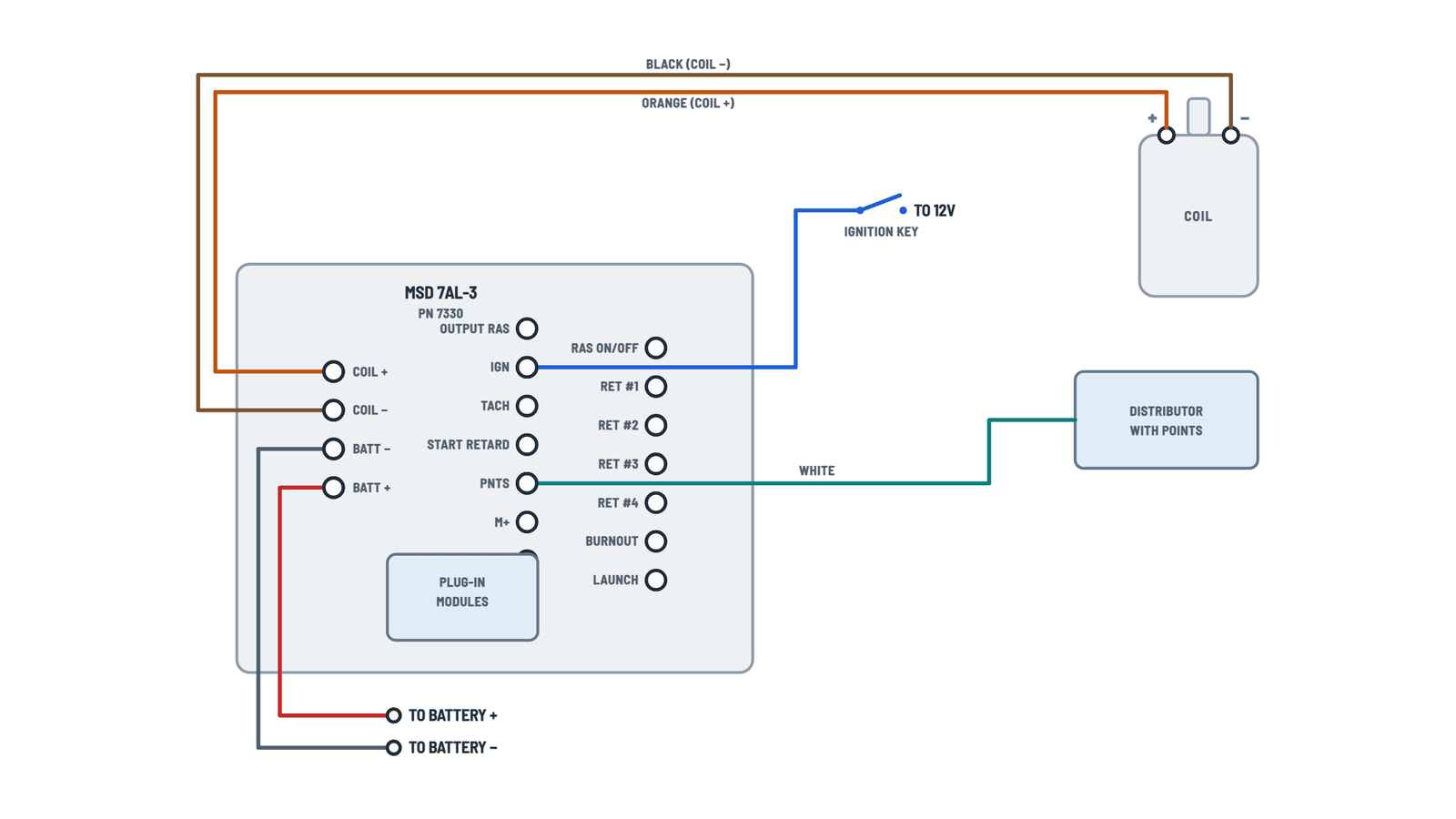
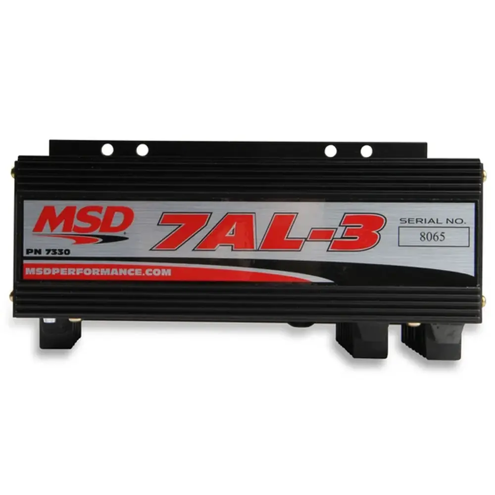
MSD 7AL-3 Ignition Control Wiring Diagram
Primary wiring
Battery, coil, IGN and the trigger: points, magnetic pickup, timing control, MSD or Mallory distributors and HEI.
Terminals and components · 9
- Battery +
- Ground
- Coil +
- Coil −
- IGN (12 V)
- Points
- Magnetic pickup
Caution
The 7AL-3 produces very high voltages: never short the battery or coil terminals.
Danger
Do not connect test equipment to the coil terminals.
Check
With a test light, IGN must have voltage with the key in On and in Start.
One trigger only
PNTS and the magnetic terminals (M+, M−) are never connected at the same time.
Other pickups
Pickup M+ M− MSD Org/blk Vio/blk MSD crank trigger Violet Green Ford Orange Purple Chrysler Org/wht Black Mallory Org/blk Vio/blk Cylinder select
Cylinders Loops to cut 8 None 6 One 4 Two Timing
The 7AL-3 retards the timing about 4° compared to other MSD ignitions: check idle and total timing after installation.
Original wire
The wire that fed the original coil + is usually used.
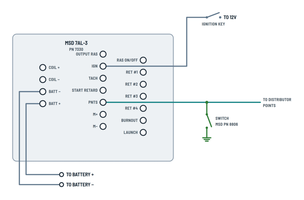
Points trigger
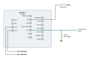
With points or an electronic amplifier only the PNTS terminal is used: the white wire comes from the points output.
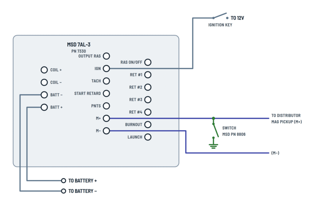
Magnetic trigger
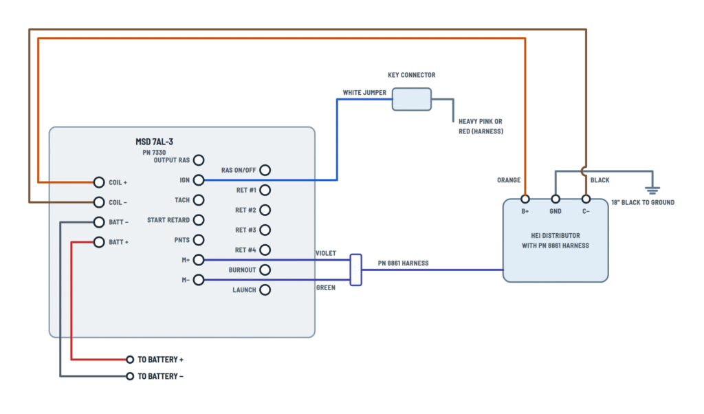
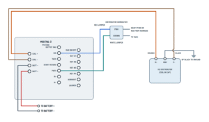
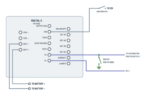
With an MSD distributor or crank trigger only M+ and M− are used: violet to M+, green to M− and the 2-pin connector to the distributor.
Distributor wires
Wire Goes to Orange PNTS (with the white wire) Red IGN (switched 12 V) Black Ground Trigger
The distributor's ignition module (PN 8360) still triggers the MSD.
Unilite wires
Wire Goes to Green PNTS (with the white wire) Red IGN (switched 12 V) Brown Ground 3-wire Mallory
All 3-wire Mallory distributors connect this way.
4-pin module
The module and its wiring are removed; the MSD PN 8861 harness connects the distributor pickup to M+ (violet) and M− (green).
Rotor bushing
A low resistance HEI rotor bushing, PN 8412, must be used with the 7AL-3.
Coil in cap
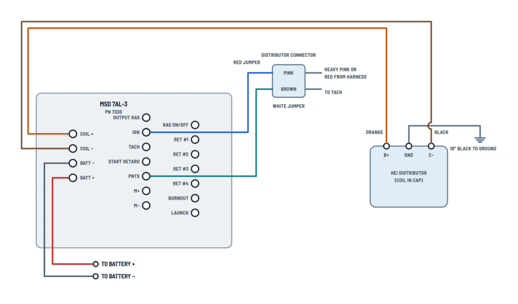
COIL+ (orange) goes to B+ and COIL− (black) to C−; the 18" black goes to ground.
Rotor bushing
A low resistance HEI rotor bushing, PN 8412, must be used with the 7AL-3.
Control wires
Wire Goes to Yellow PNTS Red IGN (switched 12 V) Pickup MSD distributor or crank trigger White Not used Key connector
The white jumper joins IGN to the key connector, which carries the vehicle's heavy pink or red wire.
Distributor connector
With the jumpers: IGN (red) to the 12 V pink and PNTS (white) to the brown, which also goes to the tach.
Optional features
Start retard, three step rev limits, rpm activated switch, tachometer and kill switch.
Terminals and components · 1
- Points
- Magnetic pickup
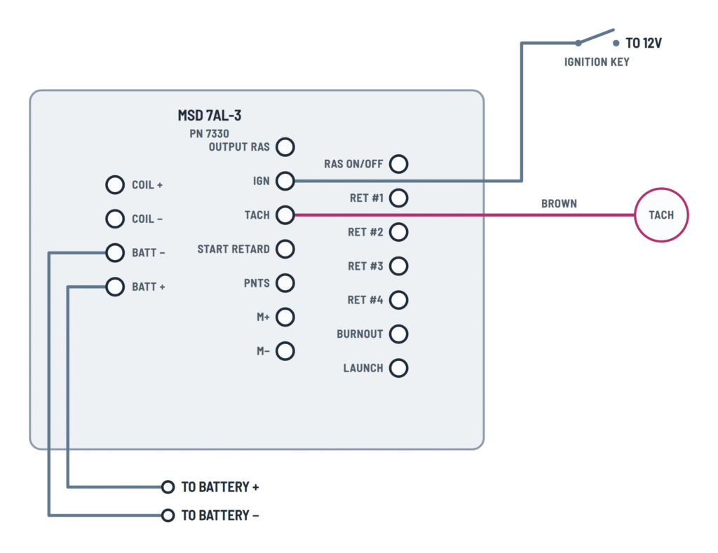
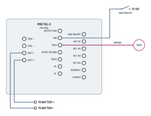
- Tach
- Start retard
- Burnout
- Launch
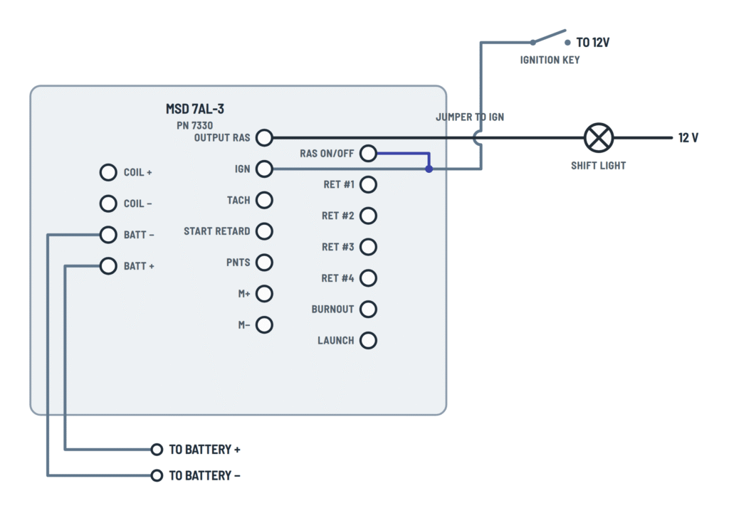
- RAS output
- RAS ON/OFF
One trigger only
PNTS and the magnetic terminals (M+, M−) are never connected at the same time.
Other pickups
Pickup M+ M− MSD Org/blk Vio/blk MSD crank trigger Violet Green Ford Orange Purple Chrysler Org/wht Black Mallory Org/blk Vio/blk Adapters
If the tach is erratic: PN 8910 with points trigger or PN 8920 with a magnetic pickup.
Switched 12 volts
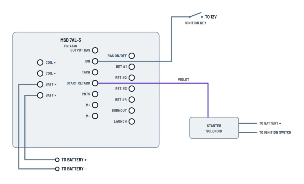
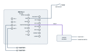
The violet wire goes from the START RETARD terminal to the starter solenoid: the timing is retarded only while cranking.
Constant 12 volts
A jumper joins START RETARD to IGN: the retard is active when the ignition is turned on and is removed at about 600 rpm; it does not return until the ignition is turned off.
Priority
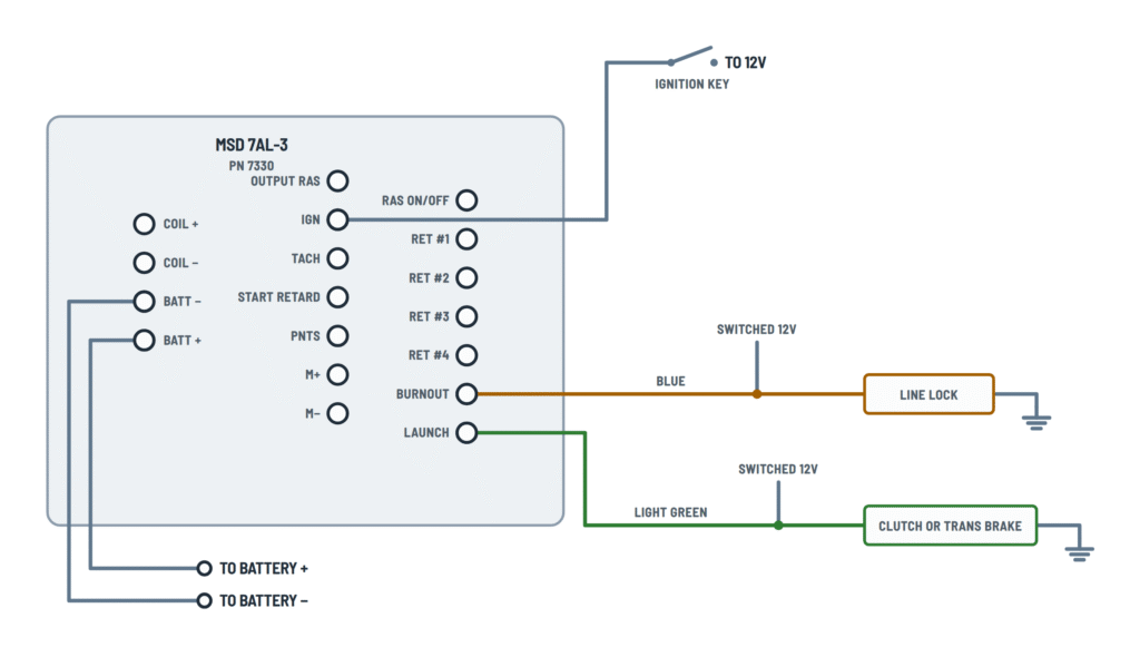
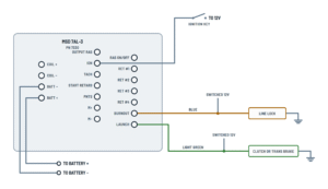
LAUNCH overrides BURNOUT; after the launch the RACE module limit is in effect.
Shift light
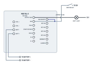
The light goes between OUTPUT RAS and 12 V: the RAS grounds it when the programmed rpm is reached.
With 12 V
If the device needs 12 V to activate, use an MSD relay PN 8960 or PN 8961.
Nitrous
With two relays, the RAS can turn on the nitrous only after the trans brake is released.
Use
With a switch on the shifter, the RAS only works in the selected gear (for example, nitrous in high gear).
Kill switch
Grounding the trigger input kills the ignition. With points, the switch goes between PNTS and ground.
Kill switch
With a magnetic pickup, the switch goes between M+ and ground: closing it kills the ignition.
RAS with a relay
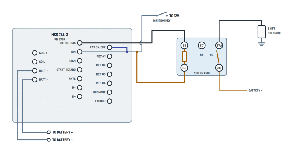
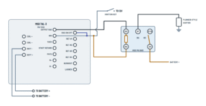
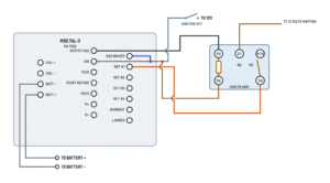
The rpm activated switch with the PN 8961 relay: plunger shifter, shift solenoid and retard.
Terminals and components · 4
- RAS output
- RAS ON/OFF
- RET #1
- Relay
With 12 V
If the device needs 12 V to activate, use an MSD relay PN 8960 or PN 8961.
Nitrous
With two relays, the RAS can turn on the nitrous only after the trans brake is released.
Use
With a switch on the shifter, the RAS only works in the selected gear (for example, nitrous in high gear).
Zero module
If a retard is not used, install a zero degree module.
Relay terminals
Terminal Goes to 85 OUTPUT RAS 86 IGN (12 V) 30 Battery + 87 Shifter solenoid Operation
At the programmed rpm the RAS grounds terminal 85: the relay closes 30–87 and the solenoid gets 12 V.
Relay terminals
Terminal Goes to 85 OUTPUT RAS 86 IGN (12 V) 30 Battery + 87A Shift solenoid Operation
The solenoid gets 12 V through the resting contact (87A); at the programmed rpm the RAS energizes the relay and removes the power.
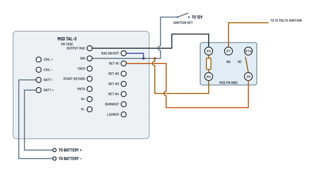
Relay terminals
Terminal Goes to 85 OUTPUT RAS 86 IGN (12 V) 87 Switched 12 V 30 RET #1 Why a relay
The RAS can only provide a ground path and the retard stages are activated with 12 V: the relay (PN 8961, supplied) does the conversion. RAS ON/OFF must have 12 V.
Solenoid
It gets 12 V through relay terminal 87; its other end goes to ground.
Solenoid
It gets 12 V through relay terminal 87A; its other end goes to ground.
About This Diagram
These diagrams are redrawn from pages 3–10 of the MSD 7AL-3 Ignition Control manual, and we offer them completely free and in English. We have also categorized it in the Ignition (Automotive) section on Diagramverse, and it has been rated by 1 user with an average rating of 5.0. If you have any specific questions about the MSD 7AL-3 Ignition Control Wiring Diagram, we suggest checking the Frequently Asked Questions (FAQs) section.
Printable MSD 7AL-3 Wiring Diagrams
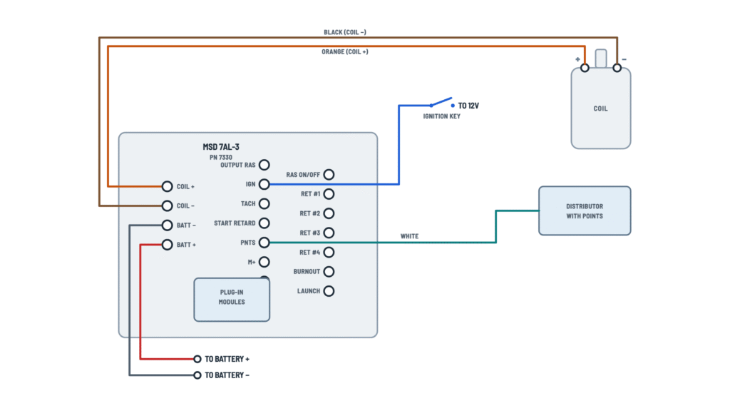
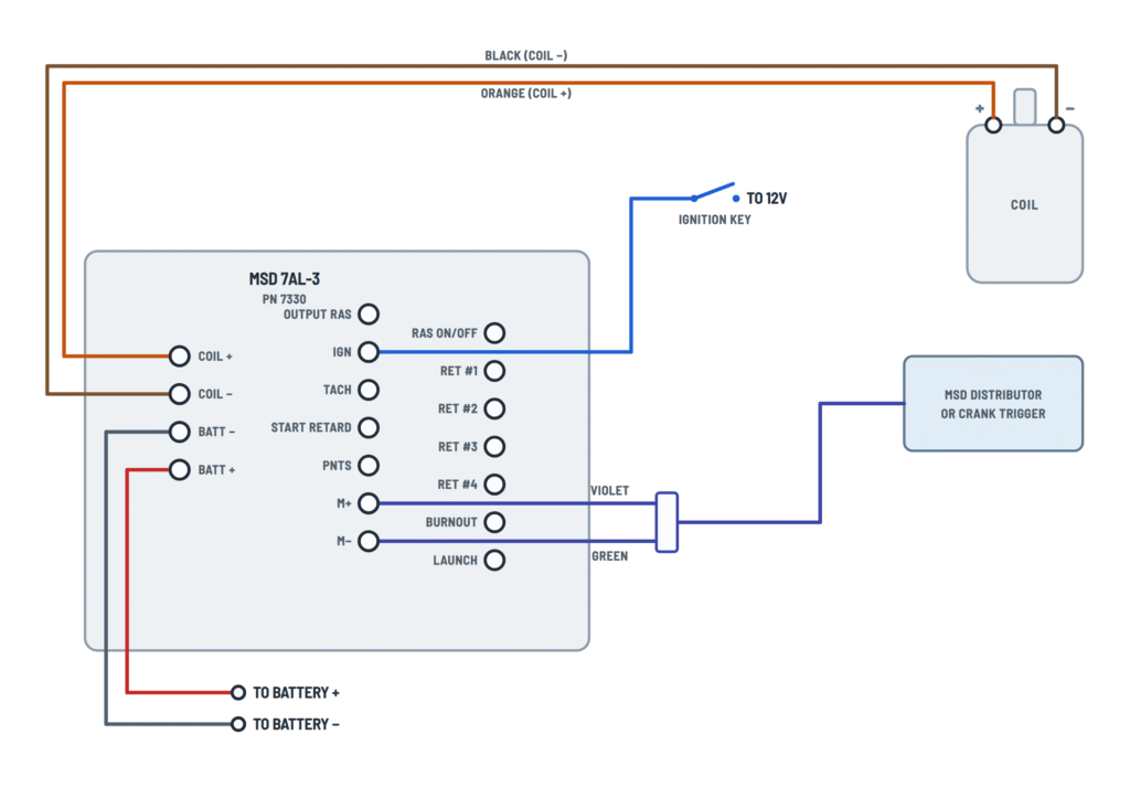

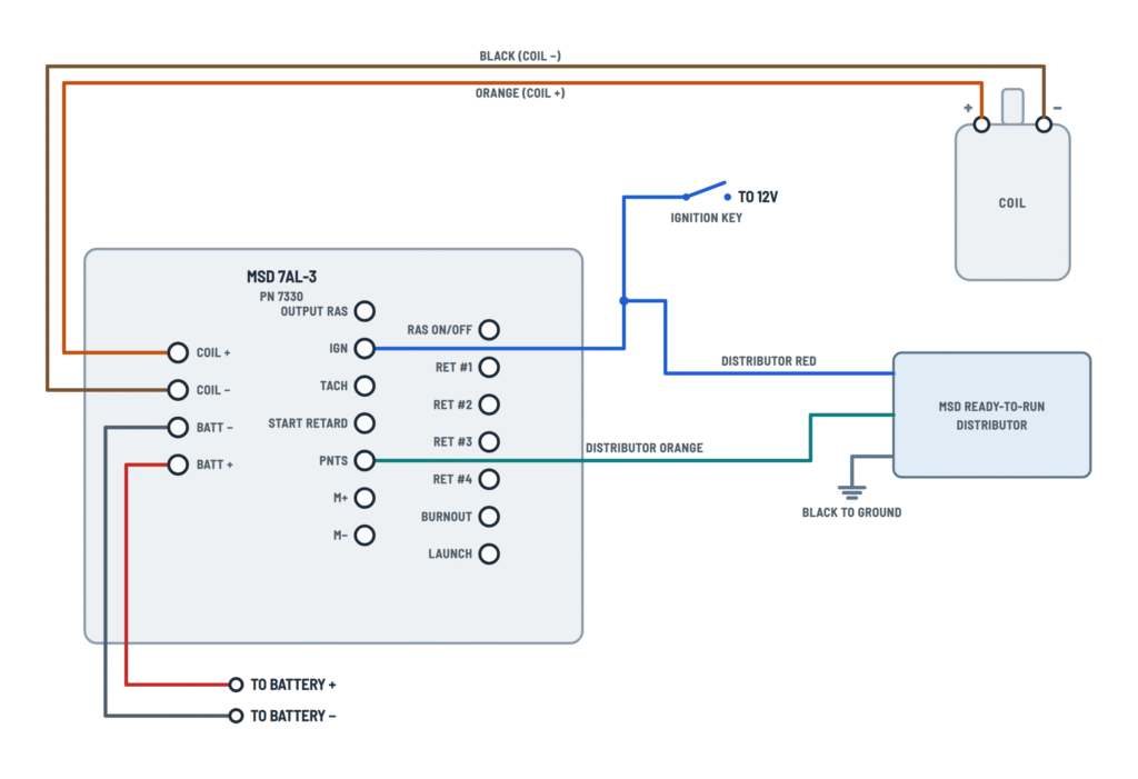
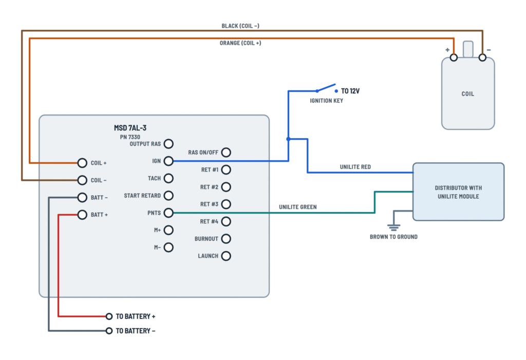







Wiring Instructions
Before you start
Pick the Primary tab variant that matches your trigger source. Use Points for a points distributor or an electronic amplifier. Use MSD 7AL-3 distributor or crank trigger for a magnetic pickup. Use Timing control if an MSD timing or boost control sits in the trigger path. For the GM HEI distributors, count the pins on the module: a 4-pin module uses 4-pin HEI (magnetic trigger), and a 5- or 7-pin module uses 5 or 7-pin HEI (points-style trigger). MSD Ready-to-Run and Mallory Unilite have their own variants. The Unilite layout also applies to other 3-wire Mallory distributors.
Gather these tools and parts:
- A drill with a 1/4" bit
- Good crimp terminals and heat-shrink to seal them
- A 12 V test light
- A timing light
- The color-coded wires from the parts bag
Use the supplied wires for their intended terminals. Following the colors makes later checks much easier. The sources don't give wire gauges, so if you have to lengthen a lead, match or exceed the gauge of the supplied wire and keep the heavy power leads as short and direct as you can.
Choose a coil and check related parts. An MSD coil gives the best results: Pro Power PN 8201 for drag racing, or HVC Pro Power PN 8251 or PN 8261 for street use and long events. With an HEI distributor that has an internal coil, you must fit the MSD Low Resistance Rotor Bushing, PN 8412.
Disconnect the battery: remove the negative cable first and reinstall it last. This is automotive 12 V work, so it doesn't need a licensed electrician or a permit. If you aren't comfortable working around high-voltage ignition parts, have a qualified race or performance shop do it.
Step-by-step wiring
- Set the cylinder count. The unit ships set for 8 cylinders. Remove the one cover screw. Cut one wire loop for an even-fire 6-cylinder engine, or two loops for a 4-cylinder. Leave both loops intact for 8 cylinders.
- Mount the box. Pick a spot away from direct engine heat. Use the unit as a template to mark the holes, drill them with the 1/4" bit, fit the vibration mounts, and secure the box with the supplied lock washers and nuts.
- Wire the power leads. On the left terminal strip, run the heavy red from BATT + directly to battery positive, and the heavy black from BATT − directly to battery negative. Don't use a fuse block, the starter stud or a chassis ground point instead.
- Wire the coil. Connect the orange from COIL + to coil positive and the black from COIL − to coil negative. Remove every other wire from the coil, including the original tach and resistor wires. On HEI distributors these wires go to the HEI B+ and C− terminals. On a 4-pin HEI, the original module and its wiring have to be removed.
- Connect the switched supply. Run the red from IGN to a source that is live in both the RUN and START key positions. On HEI variants, connect it to the key connector or to the pink wire as shown.
- Connect one trigger input only. For points-type sources, run the white wire to PNTS. For magnetic pickups, connect violet to M+ and green to M−, then plug in the 2-pin connector. Never connect both inputs at the same time. For non-MSD magnetic pickups, confirm the pickup's polarity before you connect it.
- Install the plug-in modules. Put an rpm module in the RACE holder. Put a zero-degree module in every retard socket you won't use, and in START if you won't use start retard.
- Add optional features. Use the Features and RAS + relay tabs to add these:
- TACH with the brown wire
- Start retard with the violet wire or the jumper
- BURNOUT with the blue wire and LAUNCH with the light green wire
- The RAS, with 12 V on RAS ON/OFF
- A kill switch
- Finish the connections. Make sure every terminal screw is tight, every crimp is sealed, and the wires are routed away from the headers and spark plug wires. Then reconnect the battery, positive first.
Testing and start-up
Check the IGN feed first. With the key in ON, and again in START, touch a test light to the red IGN terminal. It should light in both positions.
Crank the engine and watch the green LED. If it flashes, the unit is receiving a trigger signal. If it stays dark, the distributor or crank trigger isn't triggering the unit.
Once the engine runs, connect a timing light and check the timing at idle and at total advance. The 7AL-3 retards timing about 4° compared with other MSD ignitions, so you'll usually need to re-adjust.
Test each optional feature with 12 V on its terminal before you rely on it at the track.
Safety notes
- The COIL + output is about 570 V. Treat the coil and its leads as live whenever the key is on.
- Never short the battery or coil terminals.
- Never connect test equipment, timing-light power leads or a tach directly to the coil terminals. Use the TACH output instead.
- Keep your hands away from the plug wires and coil while cranking. Turn the key off before you touch any ignition connection.
- The heavy leads go straight to the battery, so a chafed red lead can cause a dead short. Use grommets wherever wires pass through metal.
Troubleshooting
| Symptom | Probable Cause | What to Check |
|---|---|---|
| Engine cranks but won't start, and the green LED doesn't flash | No trigger signal: the pickup connector is unplugged, the white wire is on the wrong terminal, or the wrong Primary variant was used | Confirm that only one trigger input is wired: PNTS or M+/M−, not both. Check that the 2-pin connector is seated and that the white wire lands on the correct distributor or control wire for your variant. |
| Green LED flashes while cranking but there's no spark | Coil wiring fault, a bad coil, or extra wires left on the coil | Make sure only the MSD orange is on coil + and only the MSD black is on coil −. Then do a spark test: coil wire held 1/2" from ground, key ON, and short the green and violet together (or tap the white to ground). If there's still no spark, try another coil. |
| Engine starts, then dies as soon as you release the key | IGN is fed from a circuit that is live only in START | Test-light the red IGN terminal in ON and in START. It must show 12 V in both positions. |
| Engine runs rough, misfires or backfires through the carb with a magnetic pickup | Magnetic pickup polarity is reversed | Check the pickup's color code and swap the leads so its positive wire goes to M+ (violet) and its negative to M− (green). |
| Timing seems late or power is down after installation | The normal 4° retard of the 7AL-3 hasn't been corrected, or a retard stage is active | Re-time with a timing light at idle and at total advance. Check that RET #1 to RET #4 have no stray 12 V and that unused sockets hold zero-degree modules. |
| Ignition misbehaves or breaks up under load | Power leads aren't connected directly to the battery, are loose, or the battery is weak | Run the heavy red and black straight to the battery posts and tighten them. Fully charge the battery and check that it holds about 12 V or more while cranking. |
| Engine won't rev past a low rpm | BURNOUT or LAUNCH is receiving 12 V all the time, or a low-rpm module is in the RACE holder | With the line lock and trans brake or clutch released, measure BURNOUT and LAUNCH: both should read 0 V. Check the rpm value of the module in RACE. |
| Shift light or nitrous never turns on | RAS ON/OFF has no 12 V, or the device needs 12 V instead of ground | Measure 12 V on RAS ON/OFF using the IGN jumper. The OUTPUT RAS terminal only supplies ground, up to 10 A, so for 12 V devices use the relay PN 8961 with the RAS feeding terminal 85. |
| Tachometer reads erratically or not at all | Tach is still connected to the coil, or the tach needs an adapter | Move the tach wire to the brown TACH output. If it's still erratic, fit adapter PN 8910 for a points/white trigger or PN 8920 for a magnetic pickup. |
| Engine won't run after a kill switch was added | The switch is wired so the trigger input is permanently grounded | With the switch in RUN, check for no continuity between PNTS (or M+) and ground. The switch must be single-pole single-throw and close to ground only to kill the ignition. |