MSD Digital 6 Plus Ignition Control Wiring Diagram
Basic installation
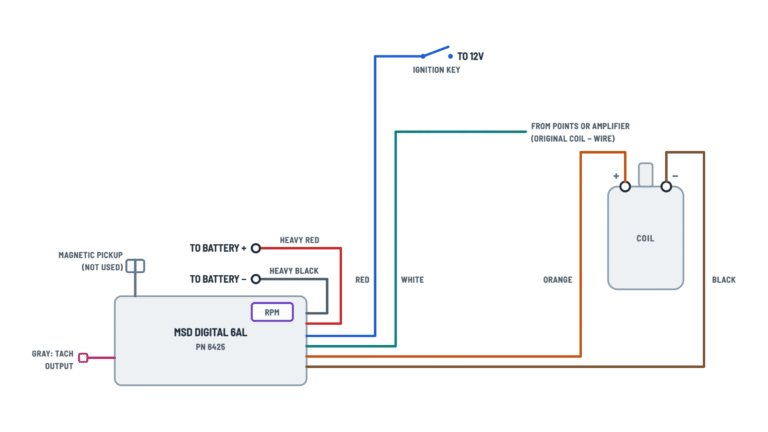
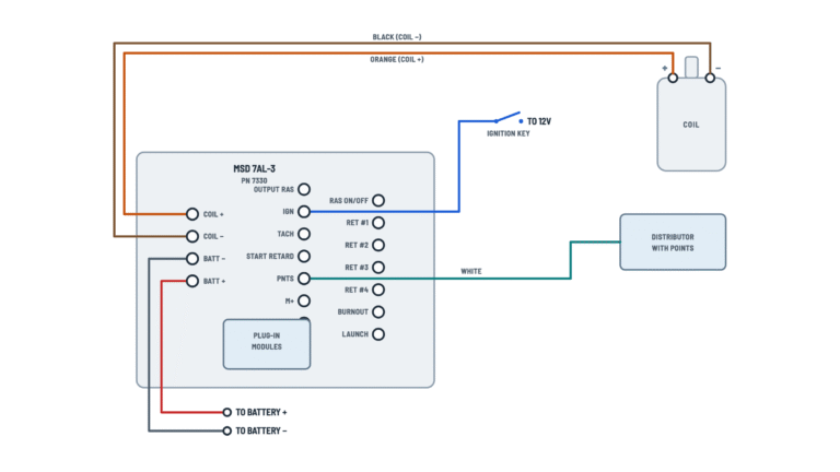
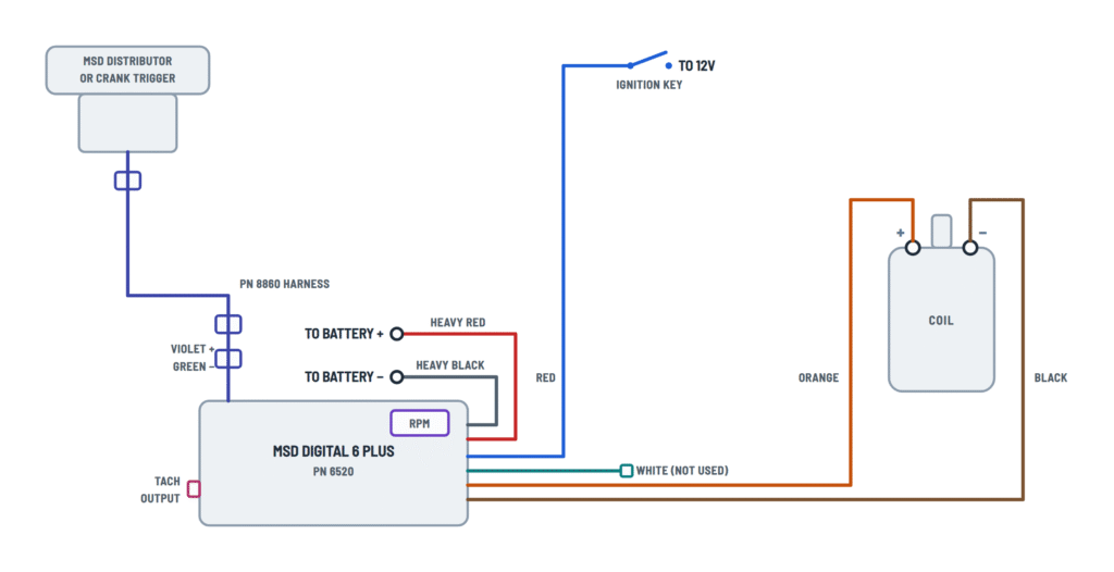
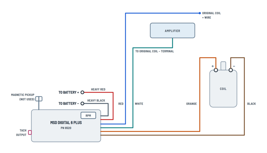
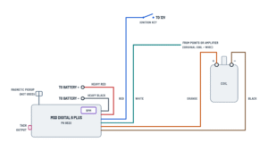
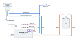
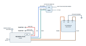
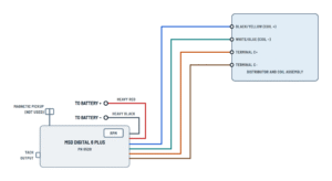
Digital 6 Plus wiring with points or amplifier trigger, or with an MSD distributor.
Terminals and components · 9
- Battery +
- Ground
- Switched 12 V
- Trigger (white)
- Magnetic pickup
- Coil +
- Coil −
Caution
Never connect it to the alternator. The ignition has an internal fuse: no other fuse is needed.
Good ground
Connect it to clean, paint-free metal and make sure there is a ground strap between the engine and the chassis.
Ballast resistor
It is not needed: if there is one in the coil wiring, bypass it.
Voltage
It must not drop below 10 V while cranking or the ignition will not fire.
Voltage
It must not drop below 10 V while cranking or the ignition will not fire.
Dual points
With dual points, remove the trailing set of points.
One trigger only
Use either the white wire or the magnetic connector, never both.
Not used
With magnetic trigger the white wire is not connected: tape it off.
One trigger only
Use either the white wire or the magnetic connector, never both.
Connection
The connector plugs straight into the MSD distributor or crank trigger with the PN 8860 harness.
Green loop (compensation)
It comes set for an MSD crank trigger or a GM pickup. With an MSD distributor or the pickup of a Ford or Chrysler distributor, cut and seal the green loop; with the white wire trigger it is not used.
Routing
Keep these wires twisted together and away from the other wires and the plug wires.
Danger
This is a capacitive discharge ignition: there is high voltage at the coil terminals. Do not touch them or connect test equipment while cranking or running.
Original wires
Remove the original coil wires: the + wire goes to the MSD red and the − wire to the white (if used).
Tachometers
If the tach does not work from this terminal, it needs an MSD adapter: PN 8920 with magnetic trigger or PN 8910 with white wire trigger (voltage triggered tachs).
Rev limits
- Max limit: 2,000 to 9,900 rpm; both dials at zero default to 12,500.
- 2 Step: 2,000 to 9,900 rpm; active with 12 V on the blue wire and overrides the max limit.
- Retard: 0 to 9.9° in 0.1° steps; active with 12 V on the pink wire and only above 2,000 rpm.
Cylinder select
Position Engine 0 / 4 4 cyl. 1 / 5 6 cyl. 2 / 6 8 cyl. 3 / 7 6 cyl. odd fire 8 / 9 Will not run (theft deterrent) Start retard
Positions 4 to 7 add a 20° start retard while cranking, up to 800 rpm.
LED
It flashes with each trigger (looks steady when running); once per second means low battery voltage or more than 27 V.
Original wire
The wire that fed the original coil + is usually used.
Distributor wires
Wire Goes to Red Switched 12 V, with the MSD red Orange MSD white (trigger) Black Ground Trigger
The 8360 distributor's ignition module still triggers the MSD.
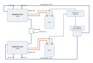
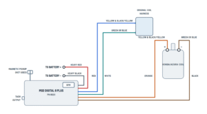
With MSD controls and dual setup
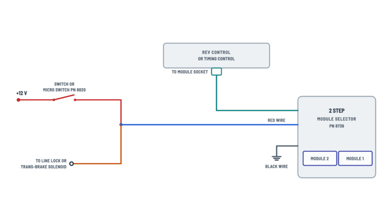
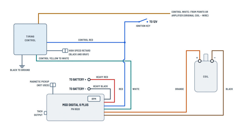
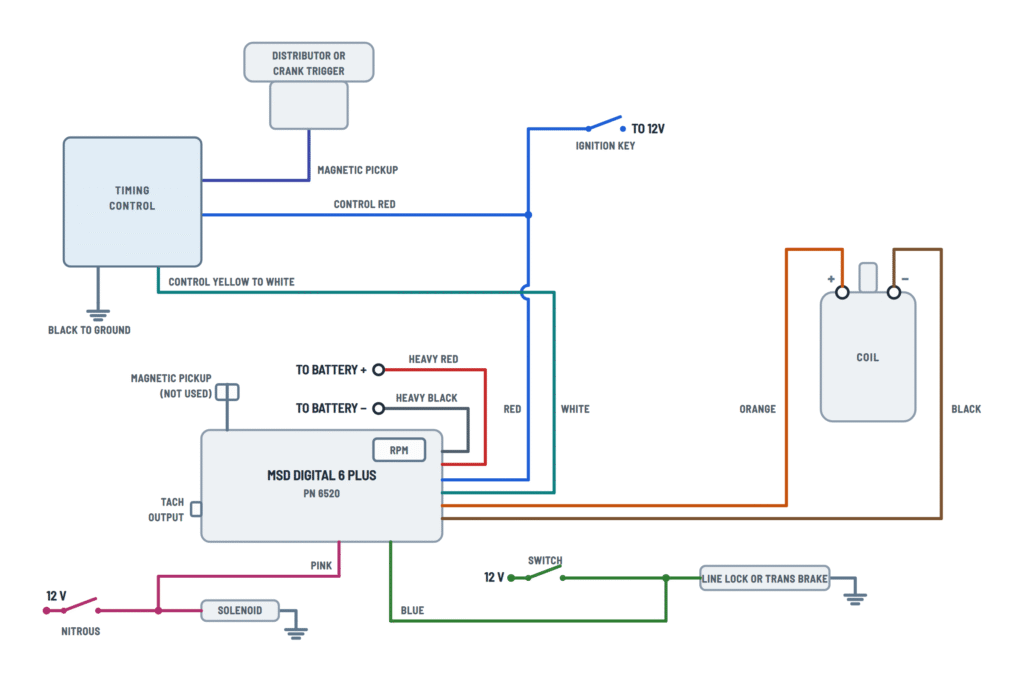
Timing control, drag race setup with 2 Step and retard, and two ignitions on the same engine.
Terminals and components · 8
- Battery +
- Ground
- Switched 12 V
- Trigger (white)
- Magnetic pickup
- Coil +
- Coil −
- Blue (2 Step)
- Pink (retard)
Caution
Never connect it to the alternator. The ignition has an internal fuse: no other fuse is needed.
Good ground
Connect it to clean, paint-free metal and make sure there is a ground strap between the engine and the chassis.
Voltage
It must not drop below 10 V while cranking or the ignition will not fire.
One trigger only
Use either the white wire or the magnetic connector, never both.
Green loop (compensation)
It comes set for an MSD crank trigger or a GM pickup. With an MSD distributor or the pickup of a Ford or Chrysler distributor, cut and seal the green loop; with the white wire trigger it is not used.
Routing
Keep these wires twisted together and away from the other wires and the plug wires.
Danger
This is a capacitive discharge ignition: there is high voltage at the coil terminals. Do not touch them or connect test equipment while cranking or running.
Original wires
Remove the original coil wires: the + wire goes to the MSD red and the − wire to the white (if used).
Control wires
Wire Goes to White Points or amplifier (original coil − wire) Yellow MSD white Red Switched 12 V, with the MSD red Black Ground Black and gray High speed retard control Knob
Controls PN 8680, 8762 and 8962 also have a plug-in adjustment knob.
Control wires
Wire Goes to Pickup Distributor or crank trigger magnetic pickup Yellow MSD white Red Switched 12 V, with the MSD red Black Ground White Not used Original wire
The wire that fed the original coil + is usually used.
Automatic selector
Both coil towers go to the automatic coil selector mounted on the distributor.
2 Step circuit
The blue wire joins the wire that feeds the line lock or trans brake solenoid: while they are on, the low (2 Step) limit is active.
Retard circuit
The pink wire joins the wire that feeds the nitrous solenoid: with the nitrous on, the retard is applied.
SPDT switch PN 8807
Sends switched 12 V to the red wire of one MSD or the other: only the selected ignition works.
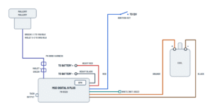
GM ignitions
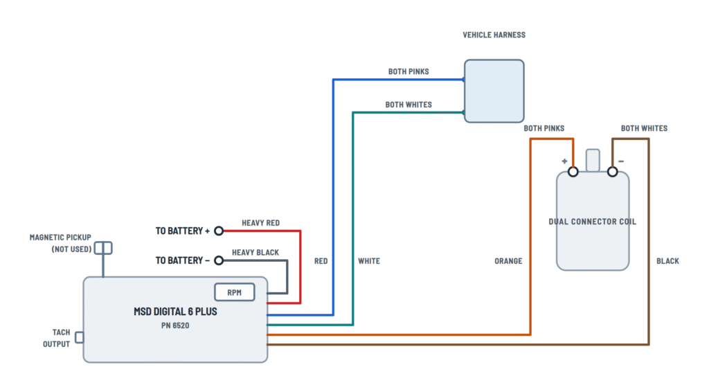
GM single or dual connector coils, MSD harnesses and HEI distributors.
Terminals and components · 7
- Battery +
- Ground
- Switched 12 V
- Trigger (white)
- Magnetic pickup
- Coil +
- Coil −
Caution
Never connect it to the alternator. The ignition has an internal fuse: no other fuse is needed.
Good ground
Connect it to clean, paint-free metal and make sure there is a ground strap between the engine and the chassis.
Voltage
It must not drop below 10 V while cranking or the ignition will not fire.
One trigger only
Use either the white wire or the magnetic connector, never both.
Green loop (compensation)
It comes set for an MSD crank trigger or a GM pickup. With an MSD distributor or the pickup of a Ford or Chrysler distributor, cut and seal the green loop; with the white wire trigger it is not used.
Routing
Keep these wires twisted together and away from the other wires and the plug wires.
Danger
This is a capacitive discharge ignition: there is high voltage at the coil terminals. Do not touch them or connect test equipment while cranking or running.
Original wires
Remove the original coil wires: the + wire goes to the MSD red and the − wire to the white (if used).
Splices
Cut and splice the two pink wires (coil +) and the two white wires (coil −). If the vehicle has no factory tach, there is only one white wire.
Plug-in harness
MSD offers a direct plug-in harness for this coil, PN 8876.
A-B-C connector
The coil connector is marked A-B-C: wire A (pink) is positive; the B and C wires are coil negative and their color varies by vehicle.
Plug-in harness
MSD offers a splice-free harness for 1996-on GM vehicles, PN 8877.
Key connector
The white jumper joins the MSD red to the key connector, which carries the vehicle's heavy pink or red wire.
Distributor connector
White connects to brown (and the tach) and red to the 12 V pink, using the jumpers supplied with the MSD.
5-pin modules
Some may hesitate or stall on deceleration; MSD offers a diode to correct it.
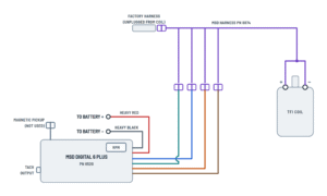
Plug-in harness
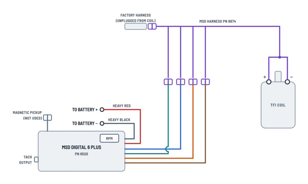
It plugs in between the factory harness and the coil: no cutting or splicing. Its red, white, orange and black leads plug into the MSD wires.
Part numbers
- PN 8876: dual connector coil.
- PN 8877: 1996-on GM vehicles.
Plug-in harness
PN 8876 (dual connector coil) or PN 8877 (1996-on GM) harness between the factory harness and the coil.
Control wires
Wire Goes to White MSD harness white lead Yellow MSD white Red Harness red lead, with the MSD red Black Ground 4-pin module
The GM ignition module is removed and replaced with the MSD PN 8861 harness, which connects the distributor pickup.
Connections
MSD wire Goes to Orange B+ Black C− Pickup 8860 harness → 8861 harness Ground
The 8861 harness wire goes to engine ground.
Connections
MSD wire Goes to Orange B+ Black C− Ground
The 18" black wire goes from the distributor to engine ground.
Ford ignitions
DuraSpark with white wire or magnetic trigger, and TFI coils with or without a harness.
Terminals and components · 7
- Battery +
- Ground
- Switched 12 V
- Trigger (white)
- Magnetic pickup
- Coil +
- Coil −
Caution
Never connect it to the alternator. The ignition has an internal fuse: no other fuse is needed.
Good ground
Connect it to clean, paint-free metal and make sure there is a ground strap between the engine and the chassis.
Voltage
It must not drop below 10 V while cranking or the ignition will not fire.
One trigger only
Use either the white wire or the magnetic connector, never both.
Green loop (compensation)
It comes set for an MSD crank trigger or a GM pickup. With an MSD distributor or the pickup of a Ford or Chrysler distributor, cut and seal the green loop; with the white wire trigger it is not used.
Routing
Keep these wires twisted together and away from the other wires and the plug wires.
Danger
This is a capacitive discharge ignition: there is high voltage at the coil terminals. Do not touch them or connect test equipment while cranking or running.
Original wires
Remove the original coil wires: the + wire goes to the MSD red and the − wire to the white (if used).
Coil connector
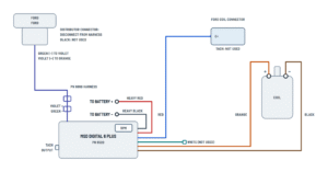
Disconnect the original coil connector: its C+ terminal (red) goes to the MSD red and its TACH terminal (green) to the white.
Coil connector
The MSD red goes to the C+ terminal of the original coil connector; the TACH terminal is not used.
TFI connector
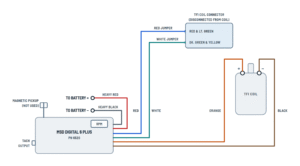
Disconnect the coil connector and plug in the red and white jumpers supplied with the MSD: red to the red & light green wire, white to the dark green & yellow wire. Seal the open end.
Ford pickup
MSD Ford distributor Green (−) Violet Violet (+) Orange — Black: not used Harness
MSD offers the PN 8869 harness to connect the magnetic connector to the DuraSpark connector.
Plug-in harness
It plugs in between the factory Ford harness and the coil, with no cutting. Its red, white, orange and black leads plug into the MSD wires.
With a timing control
It connects as with the GM harness: the white lead goes to the control's white and the control's yellow to the MSD white.
Chrysler ignitions
Chrysler electronic ignition, Dodge with a 2-pin connector and Jeep with integrated coil and module.
Terminals and components · 8
- Battery +
- Ground
- Switched 12 V
- Trigger (white)
- Magnetic pickup
- Coil +
- Coil −
Caution
Never connect it to the alternator. The ignition has an internal fuse: no other fuse is needed.
Good ground
Connect it to clean, paint-free metal and make sure there is a ground strap between the engine and the chassis.
Voltage
It must not drop below 10 V while cranking or the ignition will not fire.
One trigger only
Use either the white wire or the magnetic connector, never both.
Green loop (compensation)
It comes set for an MSD crank trigger or a GM pickup. With an MSD distributor or the pickup of a Ford or Chrysler distributor, cut and seal the green loop; with the white wire trigger it is not used.
Routing
Keep these wires twisted together and away from the other wires and the plug wires.
Danger
This is a capacitive discharge ignition: there is high voltage at the coil terminals. Do not touch them or connect test equipment while cranking or running.
Original wires
Remove the original coil wires: the + wire goes to the MSD red and the − wire to the white (if used).
Chrysler pickup
MSD Distributor Green (−) Black (M−) Violet (+) Orange (M+) Original module
The Chrysler ignition module is left disconnected.
Original wiring
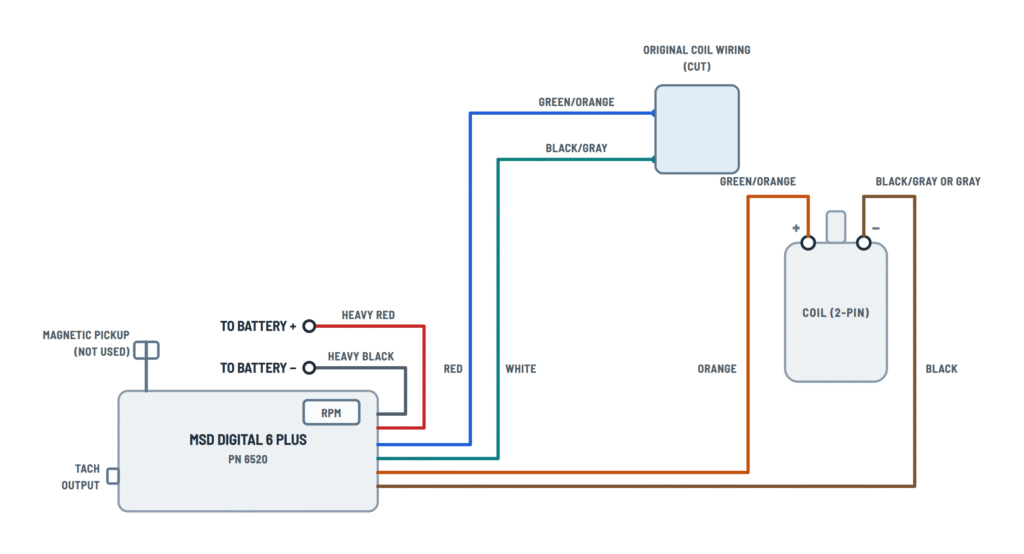
Original wire Goes to Green/orange (from the key) MSD red Black/gray (from the amplifier) MSD white Green/orange on the coil side MSD orange Black/gray or gray on the coil side MSD black Caution
The original coil wiring is cut.
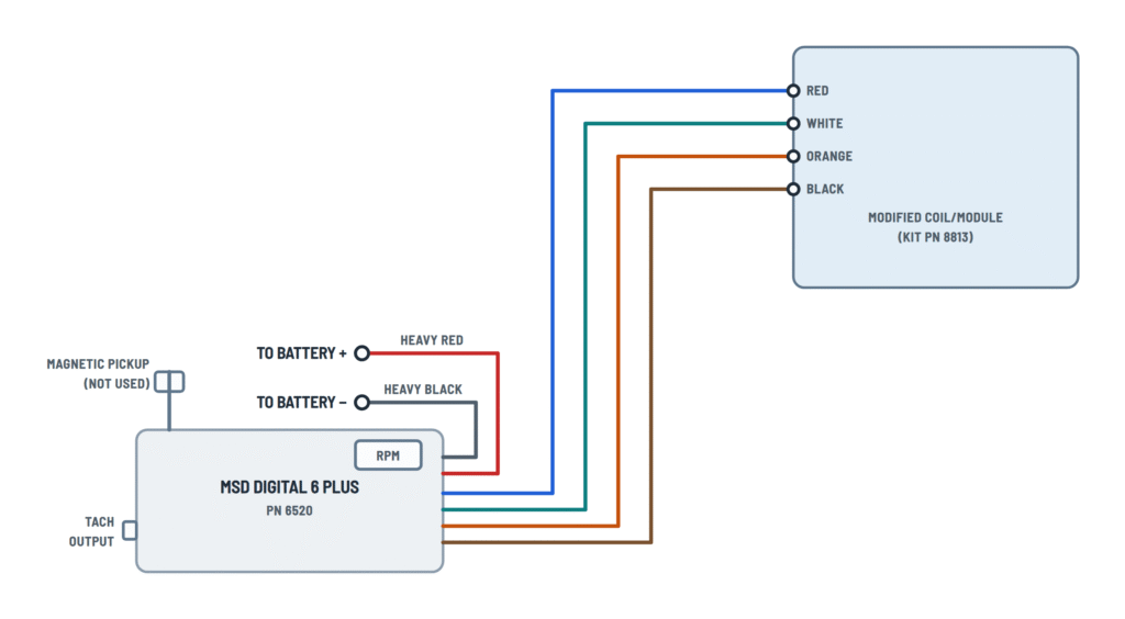
PN 8813 kit
The MSD PN 8813 kit modifies the original Jeep coil/module assembly (many 1987–1989 models). The drawing shows the coil already modified.
Caution
The original harnesses must still be connected.
Imports
Honda with internal or external coil, and general import wiring.
Terminals and components · 7
- Battery +
- Ground
- Switched 12 V
- Trigger (white)
- Coil +
- Coil −
Caution
Never connect it to the alternator. The ignition has an internal fuse: no other fuse is needed.
Good ground
Connect it to clean, paint-free metal and make sure there is a ground strap between the engine and the chassis.
Voltage
It must not drop below 10 V while cranking or the ignition will not fire.
One trigger only
Use either the white wire or the magnetic connector, never both.
Danger
This is a capacitive discharge ignition: there is high voltage at the coil terminals. Do not touch them or connect test equipment while cranking or running.
Original wires
Remove the original coil wires: the + wire goes to the MSD red and the − wire to the white (if used).
Fuel injected imports
Some will not run or lose the tach with the MSD: they need the PN 8910 adapter (Toyota and Ford Probe, the PN 8910-EIS).
Tachometers
If the tach does not work from this terminal, it needs an MSD adapter: PN 8920 with magnetic trigger or PN 8910 with white wire trigger (voltage triggered tachs).
Connections
MSD wire Goes to Red Black/yellow wire (coil +) White White/blue wire (coil −) Orange Coil terminal C+ Black Coil terminal C− Power Cap
MSD offers a Power Cap to convert internal coil Hondas to an external coil on most popular models.
Connections
MSD wire Goes to Red Black/yellow: 12 V (original coil + wire) White White/blue: trigger (original coil − wire) Original wires
Original wire Goes to Yellow & black/yellow (original +, harness side) MSD red Green or blue (original −, harness side) MSD white Yellow & black/yellow (coil side) MSD orange Green or blue (coil side) MSD black Amplifier
Remove the coil wires: the negative (from the amplifier) goes to the MSD white and the positive to the red.
Aftermarket components
Mallory distributors (magnetic or Unilite) and Pertronix ignitor.
Terminals and components · 9
- Battery +
- Ground
- Switched 12 V
- Trigger (white)
- Magnetic pickup
- Coil +
- Coil −
Caution
Never connect it to the alternator. The ignition has an internal fuse: no other fuse is needed.
Good ground
Connect it to clean, paint-free metal and make sure there is a ground strap between the engine and the chassis.
Voltage
It must not drop below 10 V while cranking or the ignition will not fire.
One trigger only
Use either the white wire or the magnetic connector, never both.
Green loop (compensation)
It comes set for an MSD crank trigger or a GM pickup. With an MSD distributor or the pickup of a Ford or Chrysler distributor, cut and seal the green loop; with the white wire trigger it is not used.
Routing
Keep these wires twisted together and away from the other wires and the plug wires.
Danger
This is a capacitive discharge ignition: there is high voltage at the coil terminals. Do not touch them or connect test equipment while cranking or running.
Original wires
Remove the original coil wires: the + wire goes to the MSD red and the − wire to the white (if used).
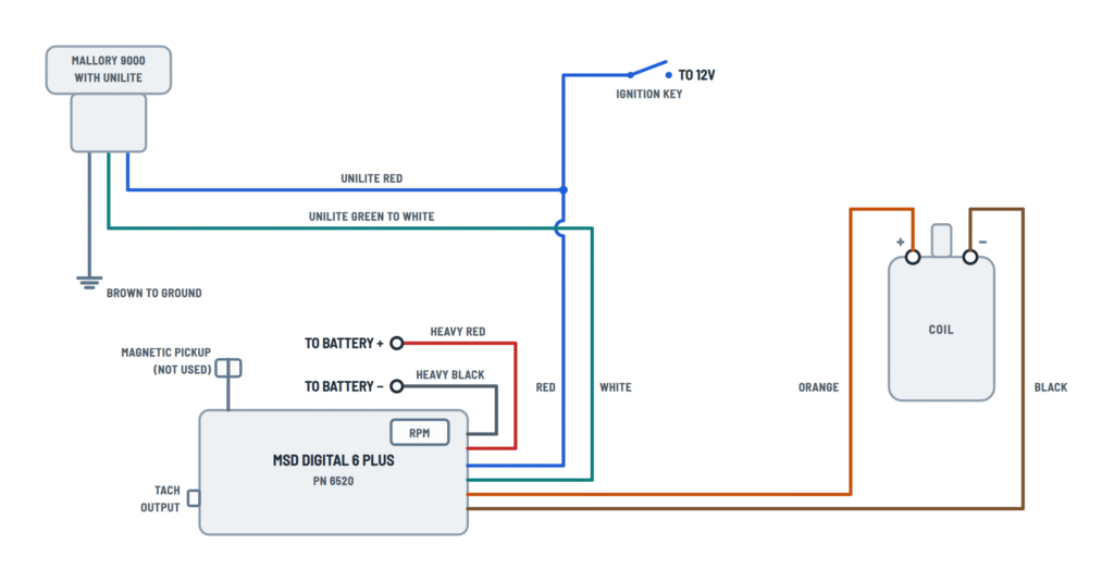
Mallory pickup
MSD Mallory Green (−) Violet/black Violet (+) Orange/black Unilite wires
Wire Goes to Red Switched 12 V, with the MSD red Green MSD white Brown Ground Pertronix wires
Wire Goes to Red Switched 12 V, with the MSD red Black MSD white Original wire
The wire that fed the original coil + is usually used.
About This Diagram
These diagrams are redrawn from pages 11–24 of the MSD Digital 6 Plus Ignition Control manual, and we offer them completely free and in English. We have also categorized it in the Ignition (Automotive) section on Diagramverse, and it has been rated by 1 user with an average rating of 5.0. If you have any specific questions about the MSD Digital 6 Plus Ignition Control Wiring Diagram, we suggest checking the Frequently Asked Questions (FAQs) section.
Printable MSD Digital 6 Plus Wiring Diagrams






















Wiring Instructions
Before you start
Start by picking the MSD Digital 6 Plus diagram that matches your car. The Basic tab covers points or an ignition amplifier, an MSD distributor or crank trigger, and the MSD 8360 distributor. MSD controls covers timing controls, drag race setups with 2 Step and retard, and a complete dual setup. The GM, Ford, Chrysler, Imports and Aftermarket tabs cover factory and third-party ignitions. To choose, first decide how the MSD gets its trigger signal. It comes either through the White wire (points, an amplifier output or an MSD control's yellow wire) or through the Magnetic pickup connector (Violet and Green). The unit never uses both at once. On a large-cap GM HEI, take off the cap and rotor and count the pins on the module (4, 5 or 7) to choose the right HEI variant.
Tools you will need: a soldering iron or a good crimper, heat-shrink tubing, a drill (1/8" bit, or 3/16" if you use the supplied vibration mounts), a multimeter, and a conventional timing light. Use helically wound spark plug wires; solid core wires will not work with this ignition. A new distributor cap and rotor are recommended. The heavy power leads are 12 gauge. You can shorten any wire. To lengthen one, go one size heavier: 10 gauge for the power leads and 16 gauge for the others, with every joint soldered and sealed.
Disconnect the battery, negative cable first. Vehicle ignition work does not normally need an electrical permit or a licensed electrician. Still, if you have not done this kind of work before, have an experienced ignition or performance shop do the installation or check it.
Step-by-step wiring
- Mount the unit in the engine compartment, away from headers, exhaust manifolds and other direct heat. Do not mount it in an enclosed space such as the glovebox. Make sure every wire reaches its connection and that you can still get to the dials.
- Prepare the original coil circuit. If there is a ballast resistor, bypass it. On dual point distributors, remove the trailing set of points. Where your diagram says to, take the original wires off the coil: the original coil negative wire usually becomes the trigger for the MSD White, and the original coil positive wire becomes the switched feed for the MSD Red.
- Run the Heavy red straight to the battery + terminal or another positive junction, such as the + side of the starter solenoid. Never connect it to the alternator. Run the Heavy black to the battery − terminal or to clean, paint-free metal on the engine. Make sure there is a ground strap between the engine and the chassis.
- Connect the small Red to a 12 V source that is live only with the key on, as your diagram shows.
- Connect the trigger. If you use the White, insulate the unused Magnetic pickup connector. If you use the Violet · Green connector, insulate the White. Twist the pickup wires together. Route all trigger wires away from the plug wires and power leads, ideally along the block or firewall.
- Set the Green Loop, the small green wire that loops out of the strain relief. Cut it and seal it for an MSD Billet distributor or for a Ford or Chrysler magnetic pickup. Leave it intact for points, factory electronic amplifiers, GM HEI and the MSD crank trigger.
- Connect the Orange to coil + and the Black to coil −. These must be the only wires on the coil terminals. Any tach or other wire that used to be on the coil goes somewhere else (see the next step).
- Connect the accessories. Wire the Blue and Pink through a switch, line-lock circuit, shifter micro-switch or nitrous activation wire so they get 12 V only when you want that function. Connect a tachometer to the Tach output with the supplied female Faston receptacle.
- Set the dials. The unit ships set for 8 cylinders. Use the cylinder select dial: 0 is 4-cyl, 1 is 6-cyl, 2 is 8-cyl, 3 is 6 odd-fire. Positions 4 to 7 are the same counts with the 20° start retard added. Positions 8 and 9 stop the engine from running. Then set the max limit, the 2 Step limit and the retard degrees.
- Reconnect the battery, negative cable last.
Testing and start-up
Before you crank, check five things: only Orange and Black are on the coil, the Red is on switched 12 V, the cylinder select is correct, the heavy leads go directly to the battery, and the engine has a ground strap. With the key on and the engine off, measure the small Red to ground. You should read about 12 V. You will not read any voltage at coil +. That is normal for a capacitive discharge ignition.
On a White wire trigger, the LED flashes for each trigger signal, so you can use it to set static timing. With the engine running above idle, the LED should look steady. Check the timing and reset it to your engine's specification, and check total timing. Use a conventional timing light; digital and dial-back lights give false readings with this ignition. The retard only works above 2,000 rpm, so test it under those conditions.
Safety notes
The unit charges its capacitor to 520 to 535 volts, and very high voltage appears at the coil terminals while you crank or run the engine. Do not touch the coil and do not connect test equipment to it at those times. The unit has reverse polarity protection and shuts down above 27 V, but you should still double-check polarity before you reconnect the battery. Before you weld on the vehicle, disconnect both heavy power leads and the tach ground wire. Keep all wiring clear of sharp edges, moving parts and exhaust heat.
Troubleshooting
| Symptom | Probable Cause | What to Check |
|---|---|---|
| Engine cranks but there is no spark at all | Small Red not on a switched 12 V source, or a bad coil or connection | With the key on, measure the small Red to ground; you should read 12 V. If you don't, use another switched source. Set the coil wire about 1/2" from ground, key on, and tap the White to ground (or short Green to Violet). You should get a spark each time you break the contact. Try a different coil. |
| Everything is wired, but the engine will not run at all | Cylinder select dial set to 8 or 9 | Set the dial to the correct position for your engine (0 to 3, or 4 to 7 with start retard). Positions 8 and 9 stop the engine from running. |
| LED flashes about once per second at idle or low rpm | Low supply voltage from a charging problem or a poor heavy lead connection | Clean and tighten the Heavy red and Heavy black at the battery. Make sure they go straight to the battery, not to the alternator. Charge the battery and check that the charging system holds at least 9 V. |
| LED flashes once per second and the ignition cuts out | Input voltage above 27 V, for example from a surge or a jump start | Check the charging system and the battery setup. The unit shuts down to protect itself and runs again once the voltage is corrected. |
| Engine keeps running after the key is turned off | Voltage feeding back to the small Red through the charging indicator lamp circuit | Install the supplied diode, facing the right direction, in the charging indicator wire. Ford: the wire to terminal 1. GM: the wire to terminal 4. 1973 to 1983 Delcotron: the smallest wire leaving the alternator, usually brown. |
| Misfire, erratic running or a jumpy tach reading | Solid core plug wires, trigger wires routed next to the plug wires, or both trigger circuits connected | Fit helically wound plug wires. Twist the Violet and Green and route them away from the other wiring. Make sure only the White or only the pickup connector is in use. |
| Timing reads wrong or drifts compared with before | Wrong Green Loop setting, or a digital or dial-back timing light | Cut and seal the loop for MSD Billet, Ford or Chrysler pickups. Leave it intact for GM HEI, points, amplifiers and the MSD crank trigger. Recheck with a conventional light. |
| Tachometer is dead or drops to zero when accelerating | Tach still on coil −, a GM inline filter, or a tach that needs an adapter | Move the tach trigger wire to the Tach output. Bypass any GM inline filter. If it still fails, use a PN 8910 with a White wire trigger or a PN 8920 with the magnetic pickup. |
| Fuel-injected import cranks but will not start after the install | Shared trigger signal too weak for the fuel injection system | Install a PN 8910 Tach Adapter. If that doesn't fix it, use the PN 8910-EIS. Toyotas and Ford Probes need the 8910-EIS. |
| 2 Step or retard does nothing | No 12 V on the Blue or Pink, or testing below 2,000 rpm | Measure 12 V on the Blue or Pink with the switch on. The retard only works above 2,000 rpm, and a 2 Step dial setting below 2,000 defaults to 2,000 rpm. |
| Hard starting on an engine with locked-out timing | Start retard not enabled | Set the cylinder select dial to the matching position from 4 to 7. Timing then retards 20° until the engine passes 800 rpm. |
| 5-pin HEI hesitates or stalls on deceleration | A known issue with some 5-pin modules | Contact MSD technical support for the bolt-in diode made for this problem. |