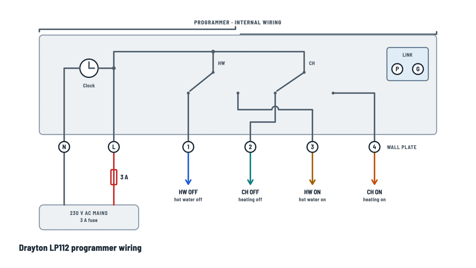
Drayton LP112 Thermostat Wiring Diagram
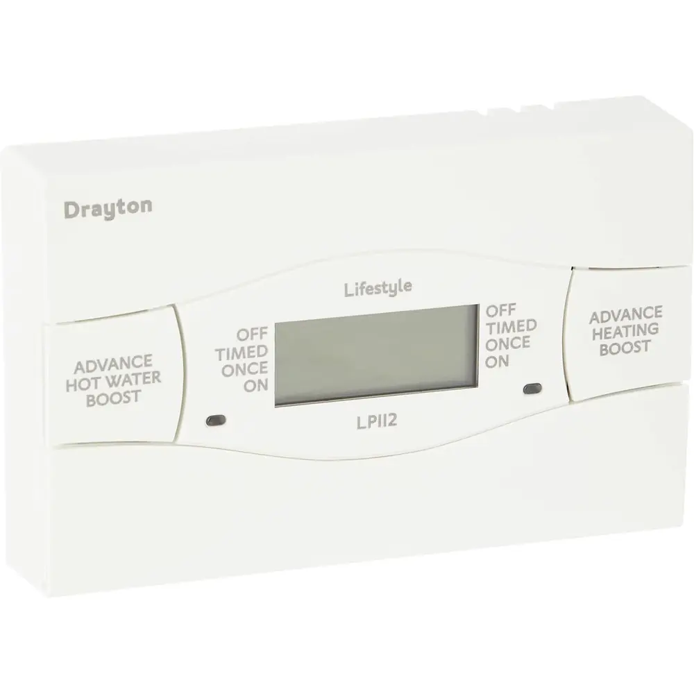
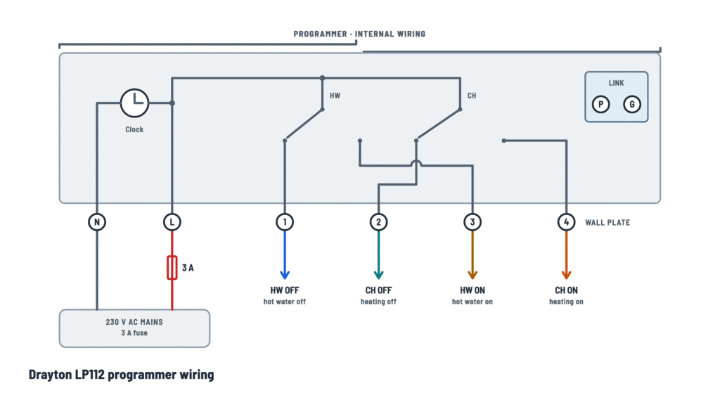
Drayton LP112 programmer wiring
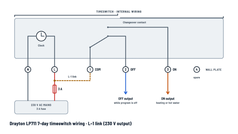
Wall plate with the 230 V mains and the hot water (HW) and central heating (CH) outputs.
Terminals and components · 7
- Live
- Neutral
- HW OFF
- CH OFF
- HW ON
- CH ON
- P/G link
Connection
Run the neutral from the same 230 V AC, 50 Hz circuit that feeds terminal L. The equipment the programmer controls takes its neutral from the junction box, not from this terminal.
Function
Inside the programmer, L feeds the clock and the commons of both changeover switches. That's why terminals 1 to 4 deliver 230 V when their switch is closed; no link is needed.
Caution
- Installation must only be carried out by a qualified electrician or heating engineer.
- Switch off the mains before starting and before removing the unit; never fit it to a live wall plate.
- The mains input must have a 3 A fuse.
Earth
The unit is double insulated and needs no earth; the wall plate has an earth loop terminal to keep the cable's earth continuous.
Connection
Use it only if the system needs a signal while hot water is off, for example the "hot water off" input of a three-port mid-position valve. Otherwise leave it free.
Caution
- The output delivers the 230 V live from L: don't use it to switch low-voltage circuits.
- Rating of each switch: 2(1) A at 230 V AC.
Connection
Usually left free. Use it only if some equipment must be powered while heating is off.
Caution
- The output delivers the 230 V live from L: don't use it to switch low-voltage circuits.
- Rating of each switch: 2(1) A at 230 V AC.
Connection
Run this terminal to the system junction box, towards the cylinder thermostat and hot water valve, which in turn call the boiler and pump.
Tip
Consult the boiler handbook for pump overrun wiring details.
Caution
- The output delivers the 230 V live from L: don't use it to switch low-voltage circuits.
- Rating of each switch: 2(1) A at 230 V AC.
Connection
Run this terminal to the system junction box, towards the room thermostat and heating valve, which in turn call the boiler and pump.
Tip
Consult the boiler handbook for pump overrun wiring details.
Caution
- The output delivers the 230 V live from L: don't use it to switch low-voltage circuits.
- Rating of each switch: 2(1) A at 230 V AC.
Settings
Setting System Operation P Fully pumped and controlled Heating and hot water are set separately. G Gravity-fed hot water Heating can't run without hot water; hot water can run alone. Check
Set the link to the system type before fitting the programmer to the wall plate.
About This Diagram
This diagram is redrawn from pages 2–3 of the Drayton LP112 Thermostat Installation Instructions, and we offer it completely free and in English. We have also categorized it in the Thermostats (HVAC & Water Heating) section on Diagramverse, and it has been rated by 1 user with an average rating of 5.0. If you have any specific questions about the Drayton LP112 Thermostat Wiring Diagram, we suggest checking the Frequently Asked Questions (FAQs) section.
Printable Drayton LP112 Wiring Diagrams
Wiring Instructions
Before you start
The Drayton LP112 is a 24-hour, dual-channel programmer. It runs on 230 V AC and sends mains voltage to your heating and hot water controls. Heating and hot water share the same on and off times. Only a qualified electrician or heating engineer should install it, using fixed wiring that meets current wiring regulations (BS 7671 in the UK). If you are not qualified, use this page to plan the job and to check the work afterwards.
Tools and materials:
- Insulated screwdrivers and wire strippers.
- A voltage tester or multimeter rated for mains voltage.
- For a flat wall: wall plugs and No. 6 x 1 in (25 mm) woodscrews.
- For a flush single conduit box type UA1 (BS4662): M3.5 x 14 bolts.
Do not use a surface mounting box. The manufacturer does not give a conductor size. Use cable suitable for a circuit protected by a 3 A fuse, as your local wiring rules require, and match the cable already used for the boiler controls.
Identify your system. The LP112 is used in three common layouts:
- a mid-position (three-port) valve system;
- a system with two spring-return two-port valves, one for heating and one for hot water;
- gravity hot water with pumped heating and a room thermostat.
The programmer terminals are the same in all three. What changes is where terminals 1 to 4 go in the junction box and how you set the System type link.
Isolate the supply. Switch off the mains isolator or fused spur. Confirm with your tester that L, N and the outputs are dead, then lock or label the isolator. Never fit the programmer to a live wall-plate.
Step-by-step wiring
- Replacing an old programmer: loosen its securing screws, unplug it and look at the wall-plate. Many plates, such as those for the Drayton Tempus 6 and 7, Honeywell ST 6200 to ST 6450 and Sunvic Select 207, already use the same N, L, 1, 2, 3, 4 layout, so the LP112 plugs straight in. On other makes, move each wire to the LP112 terminal that does the same job, and remove any links the old unit needed.
- Fitting a new wall-plate: mount it about 1.4 m above the floor with the terminals at the top. Choose a spot with good light, no condensation, no extremes of temperature, and a flat surface that covers the whole back of the unit. Leave 70 mm clear to the right, 25 mm above, and room underneath to reach the securing screws.
- Bring the cables in. For surface wiring, snap out the cable entry strip on the bottom edge of the wall-plate. Strip only enough insulation for each conductor to seat fully in its terminal.
- Connect the supply. Land the neutral on N and the live from the 3 A fused supply on L. Terminal L also feeds the common of both switches, so you do not need a link on the programmer.
- Carry the earth through. The unit is double-insulated and needs no earth of its own. Still join all the earth conductors in the earth continuity (loop) terminal, so the earth reaches the junction box, valves, pump and boiler.
- Wire the heating channel. Run CH ON (4) to the junction box terminal that feeds the room thermostat common. Connect CH OFF (2) only if your system's wiring scheme uses it.
- Wire the hot water channel. Run HW ON (3) to the junction box terminal that feeds the cylinder thermostat common. Connect HW OFF (1) only where your valve arrangement calls for it.
- Set the System type link on the back of the unit:
- P for a fully pumped system with motorized valves, which lets you run heating and hot water separately.
- G for gravity-fed hot water. You can run hot water on its own, but not heating without hot water.
- Finish the junction box wiring to match your system: room thermostat, cylinder thermostat, valves, pump and boiler. If your boiler has pump overrun, wire the pump and the boiler's permanent and switched lives exactly as the boiler handbook says.
- Final checks. Tug-test every conductor, make sure no bare copper shows, and tidy the cables so they don't push against the back of the unit. Plug the LP112 into the wall-plate and tighten the securing screws.
Testing and start-up
Confirm that the supply has a 3 A fuse, then switch on the mains. The display should light and show the correct time; the clock is set at the factory and changes for summer time automatically.
Check each output at the junction box with your meter. Measure between N and the terminal fed by each programmer output:
- Heating set to ON: about 230 V on the terminal fed by CH ON and nothing on the one fed by CH OFF.
- Heating set to OFF: the reverse.
- Hot water: repeat with HW ON and HW OFF.
The supply should read within about 207 V to 253 V. Next, turn up the room thermostat and then the cylinder thermostat. Each call should open the right valve and start the pump and boiler. Finally, set the timer mode and enter the customer's on and off times. In the factory program, ON2 and OFF2 are set to the same time, so the middle period does nothing until you change it.
Safety notes
- All four outputs carry mains voltage. A channel showing OFF is not dead: its OFF terminal is live, and so is L.
- Each switch is rated 2(1) A at 230 V. Connect only control loads such as thermostats, valves and relay coils directly. Larger loads must go through a relay or a valve auxiliary switch.
- On 28 mm valves, the white wire becomes live when the valve closes. Put it on a spare terminal so it stays safely isolated.
- Always switch off the mains before you remove the programmer from its wall-plate.
- Keep the unit within its 0 to 45°C operating range and away from condensation.
Troubleshooting
| Symptom | Probable Cause | What to Check |
|---|---|---|
| The display is blank and nothing works | No mains supply, a blown 3 A fuse, or the unit is not fully plugged into the wall-plate | Check the 3 A fuse at the spur. With the unit removed and the power on, carefully measure between L and N on the wall-plate: you should see about 230 V (207 to 253 V). Refit the unit and tighten its securing screws. |
| The programmer shows heating on, but the boiler never fires | The heating wire is on CH OFF (2) instead of CH ON (4), or the junction box doesn't carry it to the room thermostat common | With heating set to ON, measure between N and the room thermostat common: you should see about 230 V. If it only appears with heating OFF, swap terminals 2 and 4. |
| The heating runs when the programmer says it should be off | The CH ON and CH OFF wires are swapped, or the room thermostat feed comes from a permanent live | Set heating to OFF and measure at the room thermostat common: you should see 0 V. Trace the feed back to terminal 4, not to L or terminal 2. |
| The hot water never heats, but the heating works | HW ON (3) isn't connected to the cylinder thermostat, or it is on HW OFF (1) | With hot water set to ON, measure between N and the cylinder thermostat common: you should see about 230 V. Correct the wiring at the wall-plate or the junction box. |
| I can't get heating without the hot water coming on, even though I have motorized valves | The System type link is set to G on a fully pumped system | Isolate the supply, remove the unit and move the link on the back to P. |
| On my gravity hot water system, the heating and hot water don't behave as expected | The System type link is set to P on a gravity-fed hot water system | Isolate the supply, remove the unit and set the link to G. Check that the junction box follows the gravity hot water, pumped heating scheme. |
| The 3 A fuse blows as soon as a channel switches on | A short circuit on an output, a bare strand touching earth or neutral, or a load larger than the switch can handle wired directly to the output | Isolate the supply and run an insulation test on each output cable. Make sure no heavy load, such as a pump, is fed directly from terminals 1 to 4 beyond the 2(1) A rating. |
| The boiler or pump stops abruptly, or keeps running after the heating has switched off | Pump overrun wiring doesn't follow the boiler handbook, for example the permanent live and switched live are mixed up | Compare the boiler's permanent live, switched live and pump terminals with the boiler handbook. Confirm the permanent live stays at about 230 V when both channels are off. |
| The display flickers or goes blank, or outputs drop out at random | A loose conductor on L or N, or the unit is not screwed firmly to the wall-plate | Isolate the supply, re-terminate L and N, tug-test them and refit the unit with the securing screws tight. |
| There's a voltage on a valve or pump case, or the RCD trips | The earth wasn't carried through the loop terminal, so parts further along the circuit are unearthed, or a 28 mm valve's white wire is touching something | Test earth continuity from the supply to each valve, the pump and the boiler. Make sure the white wire sits on an isolated spare terminal. |