EPH Combi Pack 4 Thermostat Wiring Diagram

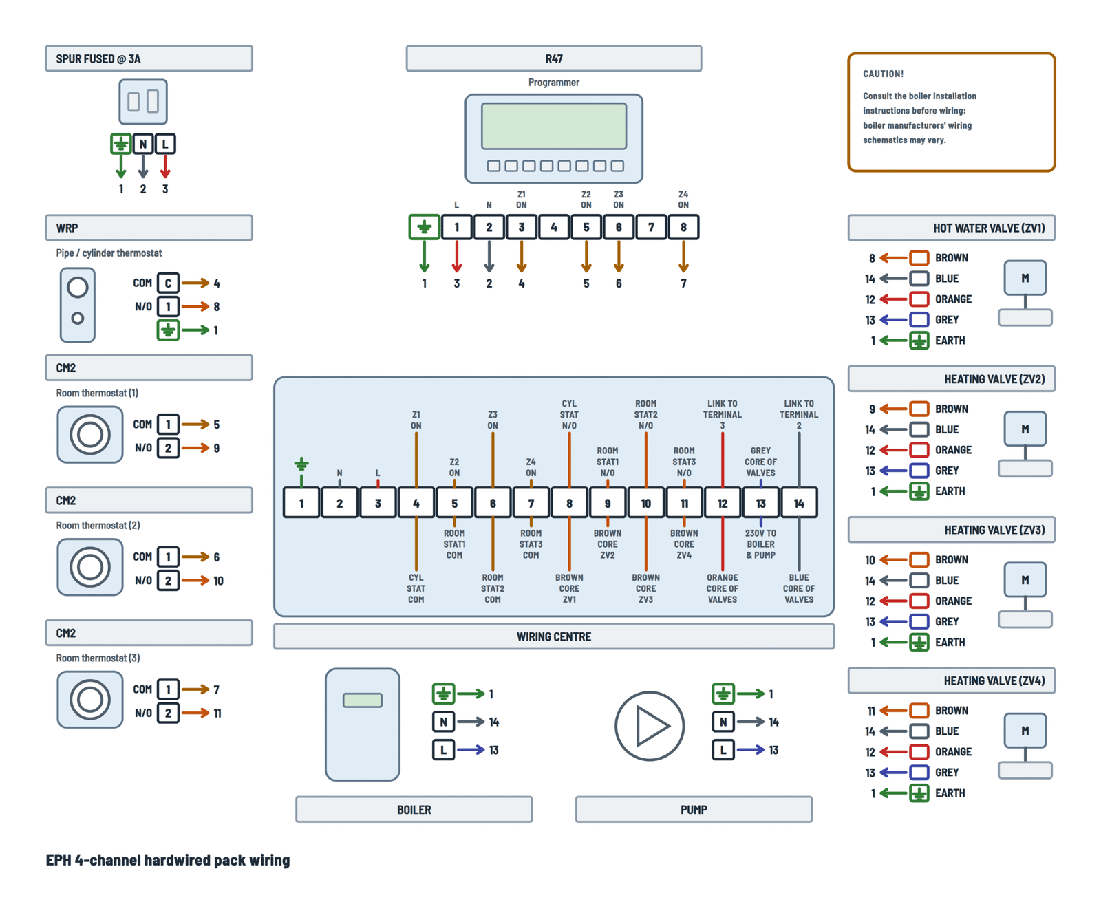
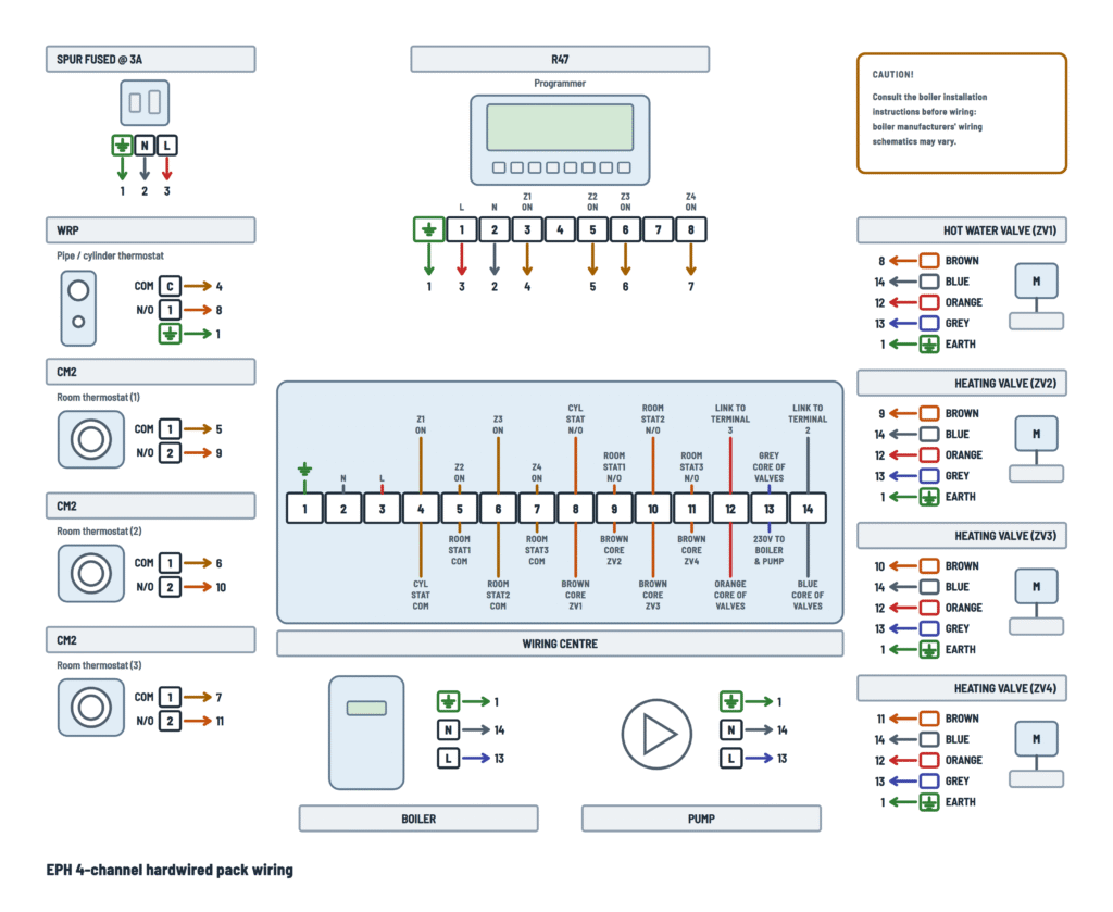
EPH 4-channel hardwired pack wiring
Each device terminal shows the number of the wiring centre terminal it goes to.
Terminals and components · 13
- Earth
- Neutral
- Live
- Z1–Z4 ON outputs
- Valve motor
- 230 V to boiler and pump
Connection
Terminal Wiring centre Function Earth 1 Protective earth N 2 Neutral L 3 230 V live Caution
- Switch off the 230 V supply before wiring or opening any unit; installation must be carried out by a qualified person.
- The spur must be fused at 3 A.
Connection
R47 terminal Wiring centre Function Earth 1 Protective earth 1 (L) 3 Live 2 (N) 2 Neutral 3 (Z1 ON) 4 Hot water: WRP cylinder thermostat 5 (Z2 ON) 5 Heating: room thermostat (1) 6 (Z3 ON) 6 Heating: room thermostat (2) 8 (Z4 ON) 7 Heating: room thermostat (3) Operation
Each ON output delivers 230 V during its channel's programmed periods. Programmer terminals 4 and 7 are not connected in this layout.
Caution
Switch off the 230 V supply before wiring or opening any unit; installation must be carried out by a qualified person.
Connection
Terminal Wiring centre Function COM (C) 4 Programmer Z1 ON (230 V during hot water periods) N/O (1) 8 Brown core (motor) of valve ZV1 Earth 1 Protective earth Operation
Contact C–1 closes when the cylinder temperature falls below the setting and opens when it is reached.
Caution
Switch off the 230 V supply before wiring or opening any unit; installation must be carried out by a qualified person.
Connection
Terminal Wiring centre Function COM (1) 5 Programmer Z2 ON (230 V during the zone's on periods) N/O (2) 9 Brown core (motor) of valve ZV2 Operation
The contact closes when the room temperature falls below the setting. COM is only live during the Z2 channel's ON periods.
Caution
Switch off the 230 V supply before wiring or opening any unit; installation must be carried out by a qualified person.
Connection
Terminal Wiring centre Function COM (1) 6 Programmer Z3 ON (230 V during the zone's on periods) N/O (2) 10 Brown core (motor) of valve ZV3 Operation
The contact closes when the room temperature falls below the setting. COM is only live during the Z3 channel's ON periods.
Caution
Switch off the 230 V supply before wiring or opening any unit; installation must be carried out by a qualified person.
Connection
Terminal Wiring centre Function COM (1) 7 Programmer Z4 ON (230 V during the zone's on periods) N/O (2) 11 Brown core (motor) of valve ZV4 Operation
The contact closes when the room temperature falls below the setting. COM is only live during the Z4 channel's ON periods.
Caution
Switch off the 230 V supply before wiring or opening any unit; installation must be carried out by a qualified person.
Connection
Core Wiring centre Function Brown 8 Motor live, from the cylinder thermostat (N/O) Blue 14 Motor neutral (14 is linked to 2) Orange 12 Switch common: permanent live (12 is linked to 3) Grey 13 Switch output: 230 V to boiler and pump Earth 1 Protective earth Operation
When the thermostat closes, the motor opens the valve; once fully open, the switch connects orange and grey and puts live on terminal 13, which fires the boiler and pump. Any one of the four valves being open is enough.
Check
If the boiler needs a volt-free signal from the valves' switches, the orange and grey cores don't go to terminals 12 and 13: follow the boiler manufacturer's schematic.
Connection
Core Wiring centre Function Brown 9 Motor live, from room thermostat (1) Blue 14 Motor neutral (14 is linked to 2) Orange 12 Switch common: permanent live (12 is linked to 3) Grey 13 Switch output: 230 V to boiler and pump Earth 1 Protective earth Operation
When the thermostat closes, the motor opens the valve; once fully open, the switch connects orange and grey and puts live on terminal 13, which fires the boiler and pump. Any one of the four valves being open is enough.
Check
If the boiler needs a volt-free signal from the valves' switches, the orange and grey cores don't go to terminals 12 and 13: follow the boiler manufacturer's schematic.
Connection
Core Wiring centre Function Brown 10 Motor live, from room thermostat (2) Blue 14 Motor neutral (14 is linked to 2) Orange 12 Switch common: permanent live (12 is linked to 3) Grey 13 Switch output: 230 V to boiler and pump Earth 1 Protective earth Operation
When the thermostat closes, the motor opens the valve; once fully open, the switch connects orange and grey and puts live on terminal 13, which fires the boiler and pump. Any one of the four valves being open is enough.
Check
If the boiler needs a volt-free signal from the valves' switches, the orange and grey cores don't go to terminals 12 and 13: follow the boiler manufacturer's schematic.
Connection
Core Wiring centre Function Brown 11 Motor live, from room thermostat (3) Blue 14 Motor neutral (14 is linked to 2) Orange 12 Switch common: permanent live (12 is linked to 3) Grey 13 Switch output: 230 V to boiler and pump Earth 1 Protective earth Operation
When the thermostat closes, the motor opens the valve; once fully open, the switch connects orange and grey and puts live on terminal 13, which fires the boiler and pump. Any one of the four valves being open is enough.
Check
If the boiler needs a volt-free signal from the valves' switches, the orange and grey cores don't go to terminals 12 and 13: follow the boiler manufacturer's schematic.
Connection
Terminal Wiring centre Function Earth 1 Protective earth N 14 Neutral (14 is linked to 2) L 13 Live switched by the valves' limit switches Caution
- Consult the boiler installation instructions before wiring: boiler manufacturers' wiring schematics may vary.
- A permanent power supply may be required.
- An overrun function may be required.
- A volt-free signal from the motorised valves' limit switches may be required.
Connection
Terminal Wiring centre Function Earth 1 Protective earth N 14 Neutral (14 is linked to 2) L 13 Live switched by the valves' limit switches Check
If the boiler needs a pump overrun, the pump may have to go to the terminals the boiler manufacturer specifies instead of terminal 13.
Links
Link Carries To 12 – 3 Permanent live Orange cores (switch commons) 14 – 2 Neutral Valves' blue cores, boiler and pump Check
Check whether the wiring centre already has these links fitted; if not, make them with wire of the same size as the supply.
About This Diagram
This diagram is redrawn from page 1 of the EPH Combi Pack 4 Thermostat Wiring Diagram, and we offer it completely free and in English. We have also categorized it in the Thermostats (HVAC & Water Heating) section on Diagramverse, and it has been rated by 1 user with an average rating of 5.0. If you have any specific questions about the EPH Combi Pack 4 Thermostat Wiring Diagram, we suggest checking the Frequently Asked Questions (FAQs) section.
Printable EPH Combi Pack 4 Wiring Diagrams
Wiring Instructions
Before you start
This EPH Combi Pack 4 diagram shows the EPH 4-channel hardwired pack (CR4P, CR422P and CR428P). The pack contains an R47 4-channel programmer, a WRP pipe/cylinder thermostat, three CM2 room thermostats, four 2-port motorized valves and a 14-terminal wiring centre. ZV1 is the hot water valve and ZV2 to ZV4 are the heating valves. Some CombiPack4 kits instead come with a battery-powered RFRP-OT thermostat and an RF1A-OT wireless receiver. If that is your kit, this layout does not apply: wire the receiver from its own terminal diagram.
- Tools: insulated screwdrivers, wire strippers, a multimeter or approved two-pole voltage tester, cable labels and bootlace ferrules for stranded cores.
- Cable: the sources do not specify a size. Every circuit here carries 230 V, so use mains-rated cable with an earth conductor, sized to your local wiring regulations. Each valve has five cores: brown, blue, orange, grey and earth.
- Supply: feed the whole system from one 3 A fused spur. The 3 A fuse is the only protective device the system relies on.
- Isolation: switch off and lock off the spur, take out the fuse and prove the circuit dead before you touch any terminal.
- Who should do it: this is mains wiring that controls a boiler. Have a qualified electrician or heating engineer do it, and check whether your area requires the work to be notified or certified.
Read the boiler installation instructions before you wire anything. Boiler wiring varies: some boilers need a permanent live supply, some need a pump overrun, and some need a volt-free signal from the valve limit switches instead of the switched live shown on terminal 13. If your boiler needs any of these, its connection will differ from the drawing.
Step-by-step wiring
- Mount the wiring centre, the R47 programmer and the thermostats. Put each CM2 about 1.5 metres above the floor, in the zone it controls, away from direct sunlight, radiators and drafts. Fit the WRP to the cylinder as its instructions describe.
- Run the supply from the 3 A fused spur to the wiring centre: Earth to 1, N to 2 and L to 3. Keep the spur off.
- Fit the two links in the wiring centre: 12 to 3 (live for the orange valve cores) and 14 to 2 (neutral for the blue cores, the boiler and the pump).
- Power the R47 from terminals 1, 2 and 3. Then connect its outputs: Z1 ON to 4, Z2 ON to 5, Z3 ON to 6 and Z4 ON to 7.
- Wire the WRP: COM to 4 and N/O to 8.
- Wire the room thermostats on their COM and N/O terminals: CM2 (1) to 5 and 9, CM2 (2) to 6 and 10, and CM2 (3) to 7 and 11. Always use the N/O contact, which closes when the room calls for heat.
- Connect the valve motors. Run the brown cores to their own terminals: ZV1 to 8, ZV2 to 9, ZV3 to 10 and ZV4 to 11. All four blue cores go to 14.
- Connect the valve switches. All four orange cores go to 12, all four grey cores go to 13, and every valve earth goes to 1. Terminals 12, 13 and 14 each take several cores, so ferrule them and make sure every strand is clamped.
- Connect the boiler: L to 13, N to 14 and earth to 1. Do this only if the boiler manual agrees with this arrangement.
- Connect the circulating pump in parallel with the boiler: L to 13, N to 14 and earth to 1.
- Label every cable, tug-test every terminal, dress the cores neatly and refit all covers.
Testing and start-up
Before you apply power, check that there is earth continuity from terminal 1 to each valve, the boiler, the pump and the spur. Also check that there is no continuity between live and earth.
- Switch on the spur. Measure about 230 V between 3 and 2, and between 3 and 1.
- With every programmer channel OFF and all valves closed, you should read 0 V between 13 and 14. The boiler and pump should stay off.
- Turn Z1 ON and turn the WRP up. You should read 230 V at terminal 4, then at 8, and ZV1 should drive open. When it is fully open, its orange–grey switch closes, terminal 13 goes live, and the boiler and pump start.
- Turn the WRP down. ZV1 should close and terminal 13 should go dead, as long as no other valve is open.
- Repeat the test for Z2 with CM2 (1) and ZV2, Z3 with CM2 (2) and ZV3, and Z4 with CM2 (3) and ZV4. Each time, confirm that the correct valve moves.
- Finish by setting the clock and switching times on the programmer and the temperatures on each thermostat.
Safety notes
- Every part of this system works at 230 V, including the thermostats and the valve switch cores. Treat terminals 2 to 14 as live whenever the spur is on.
- Terminal 13 can be live from any valve switch even when the thermostat you are working on is off. If the boiler has its own permanent supply, isolate that as well before you work.
- Never replace the 3 A fuse with a higher rating to cure nuisance blowing. Find the fault first.
- Earth every valve, the boiler and the pump at terminal 1.
Troubleshooting
| Symptom | Probable Cause | What to Check |
|---|---|---|
| Nothing works at all, and the programmer display is blank | 3 A fuse blown, spur switched off, or the supply is not on terminals 2 and 3 | Measure between 3 and 2 at the wiring centre: you should read about 230 V. If you read nothing, check the spur switch and the 3 A fuse, then the L and N connections. |
| A zone is ON at the programmer and the thermostat is turned up, but its valve never opens | Thermostat wired to the wrong contact, or COM not on the matching programmer output | When the thermostat calls for heat, measure from its COM terminal (4 to 7) to 14, then from its N/O terminal (8 to 11) to 14. Both should read 230 V. Move the wire to the N/O contact if needed. |
| The valve opens but the boiler and pump don't start | Link 12–3 missing, or the orange or grey core not on 12 or 13 | Measure 230 V between 12 and 14. With the valve fully open, terminal 13 should also read 230 V. If it doesn't, check the orange and grey terminations. |
| No valve moves even though 230 V reaches its brown core | Link 14–2 missing or blue cores not landed on 14 | With power off, check continuity from 14 to 2 and from 14 to each blue core. Refit the 14–2 link. |
| The wrong room heats up, or hot water comes on when a room calls | Brown cores swapped between terminals 8 to 11, or a thermostat landed on the wrong pair | Turn on one zone at a time and note which valve opens. Each brown core must match its thermostat's N/O terminal. |
| The boiler and pump run all the time, even with everything off | A grey core landed on 12, terminals 12 and 13 bridged, or a valve switch stuck closed | With all zones OFF, terminal 13 should read 0 V. Disconnect the grey cores one at a time to find the one that keeps it live. |
| Hot water heats even when Z1 is switched OFF | WRP COM fed from permanent live on 3 instead of terminal 4 | With Z1 OFF, measure terminal 4 to 14: you should read 0 V. Make sure the WRP COM is on 4 only. |
| The fuse blows as soon as a thermostat calls for heat | The thermostat's N/O or a brown core is landed on neutral (terminal 14 or 2) | Isolate the supply and trace the N/O wire of the thermostat that was calling. It must go to 8, 9, 10 or 11, never to 14. |
| There's 230 V on terminal 13 but the boiler still won't fire | The boiler needs a volt-free contact or a permanent live instead of a switched live | Check the boiler's wiring instructions and rewire its control input to suit. |
| The boiler locks out or overheats right after the heating switches off | The boiler needs a pump overrun, but the pump is fed from 13 and stops immediately | Check the boiler manual for overrun and permanent supply terminals. If required, wire the pump from the boiler's overrun output. |
| You feel a tingle from a valve or pipework, or an RCD trips occasionally | A missing or loose earth at terminal 1, or a damaged core touching metal | With power off, check continuity from terminal 1 to each valve, the pump and the boiler, and retighten every earth. Run an insulation test from live to earth. |