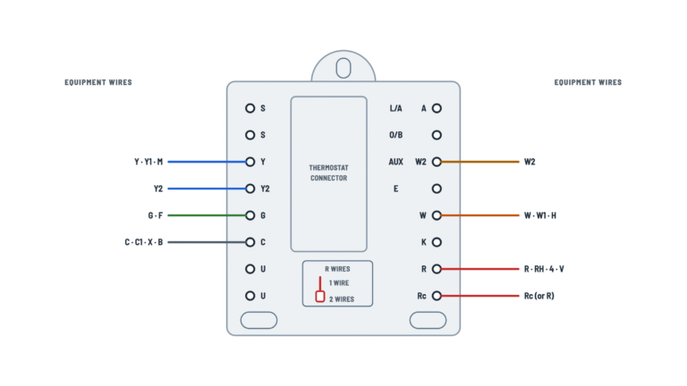
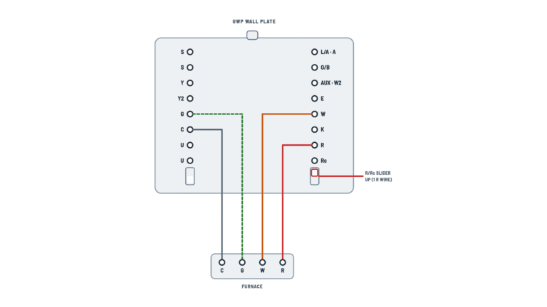
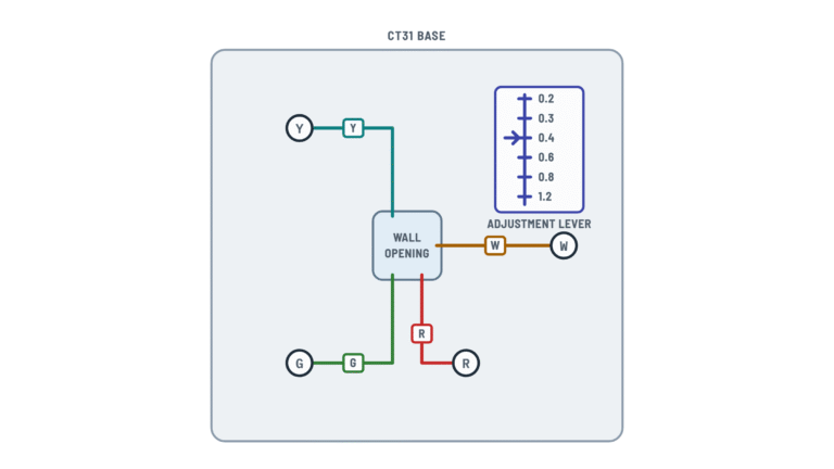
Honeywell T874R Thermostat Wiring Diagram
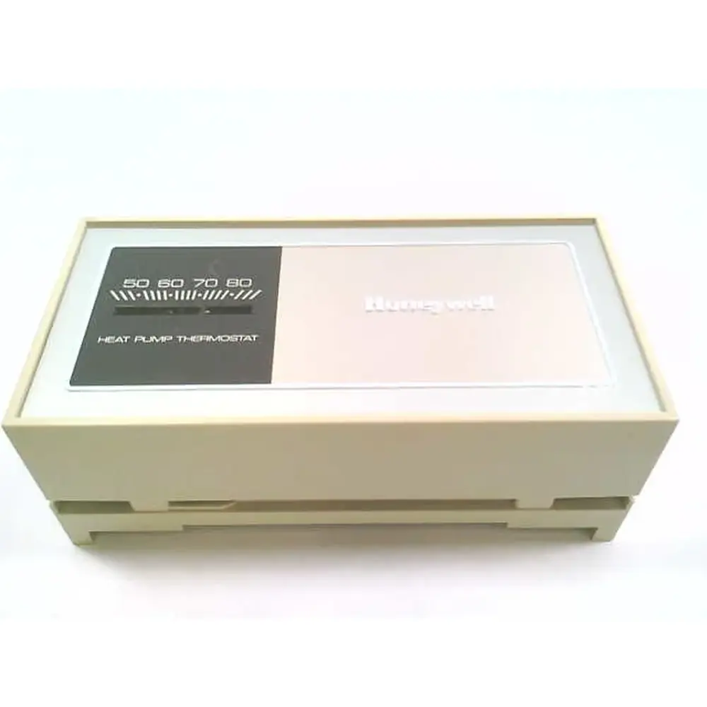
Honeywell models
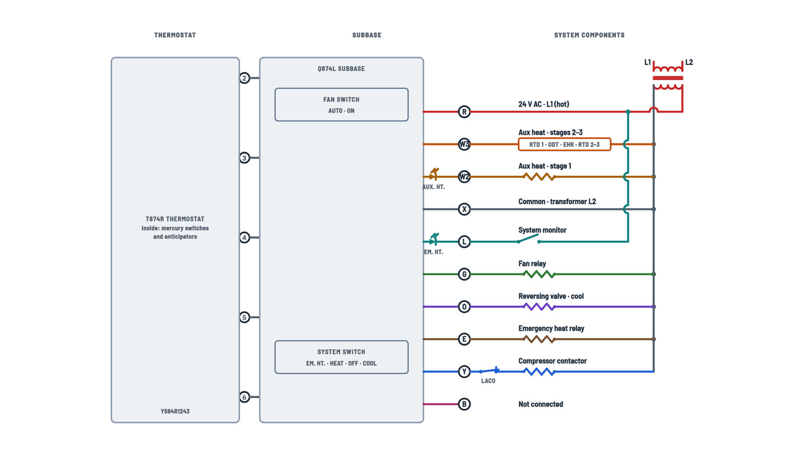
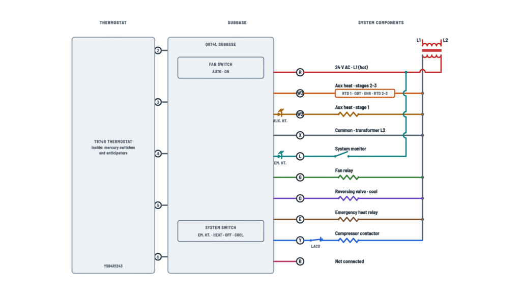
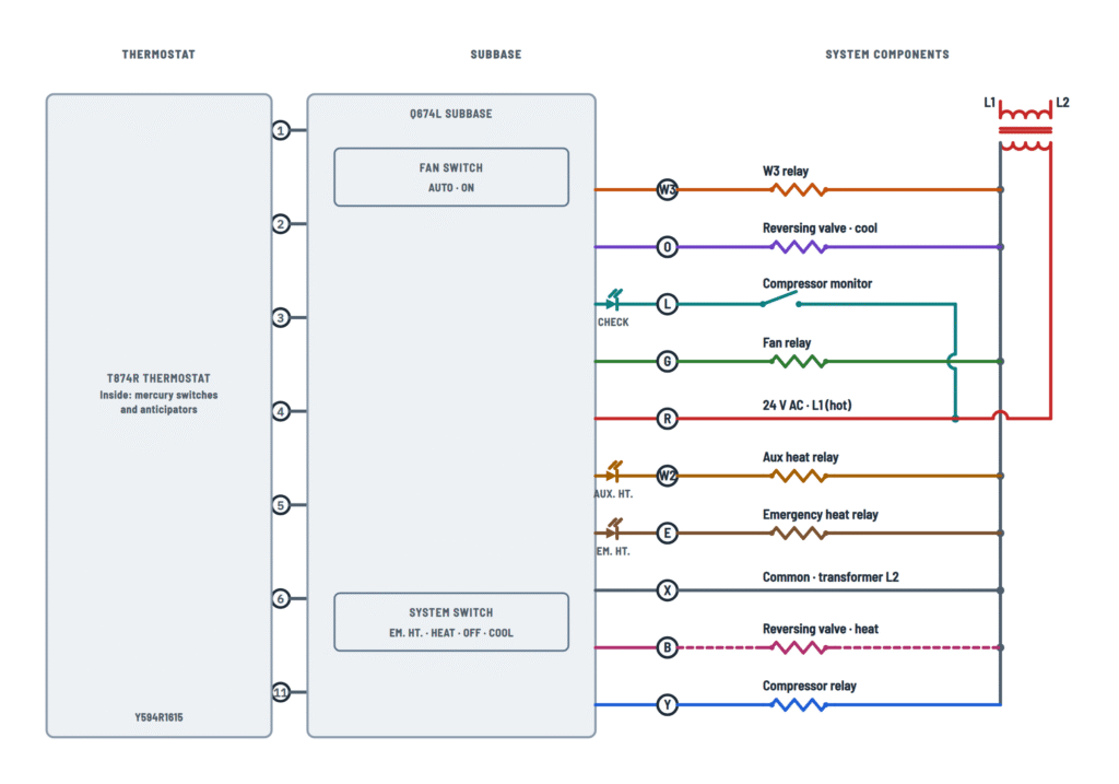
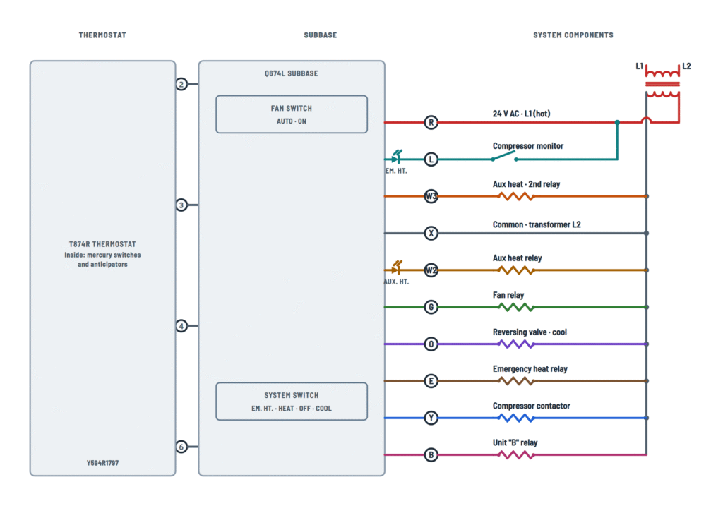
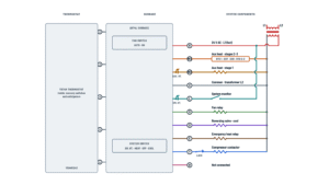
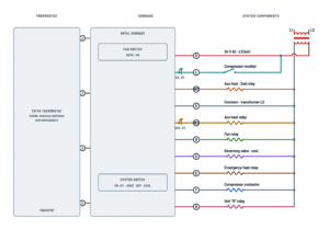
T874R1152, 1475, 1616, 1822 and 1988: common on X, auxiliary heat on W2/W3 and emergency heat on E.
Terminals and components · 11
- R · 24 V
- Common
- Fan
- Compressor
- Reversing
- Aux heat
- Emergency
- Monitor
- B output
- Optional or jumper
Model
Package Y594R1243: T874R1152 thermostat on the Q674L1207 subbase.
Data
- LEDs: AUX. HT. (green, on some models) and EM. HT. (red)
- Reversing valve energized in cooling (O)
- Adjustable stage 2 heat anticipator; stage 1 fixed
Anticipator setting (stage 2)
With the thermostat removed and power on, connect an AC ammeter between W2 and R, set the switch to HEAT and read the current after one minute. Set the anticipator to that value; if the unit cycles too fast, raise it half a division at a time.
Mounting
Level the subbase with a spirit level: if it is off level, the (mercury) thermostat drifts from the setpoint. One wire per terminal except factory jumpers, and plug the cable hole to stop drafts.
Caution
Turn the power off before wiring. The thermostat contains mercury: recycle it when replaced.
Model
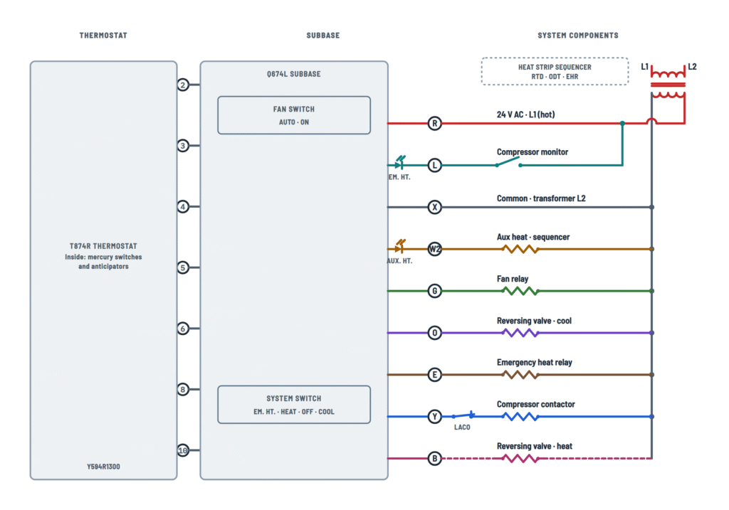
Package Y594R1300: T874R1475 thermostat on the Q674L1520 subbase.
Data
- LEDs: AUX. HT. and EM. HT. (also signals compressor fault)
- Reversing valve on O (cooling) or B (heating)
- Fixed heat anticipation
Mounting
Level the subbase with a spirit level: if it is off level, the (mercury) thermostat drifts from the setpoint. One wire per terminal except factory jumpers, and plug the cable hole to stop drafts.
Caution
Turn the power off before wiring. The thermostat contains mercury: recycle it when replaced.
Model
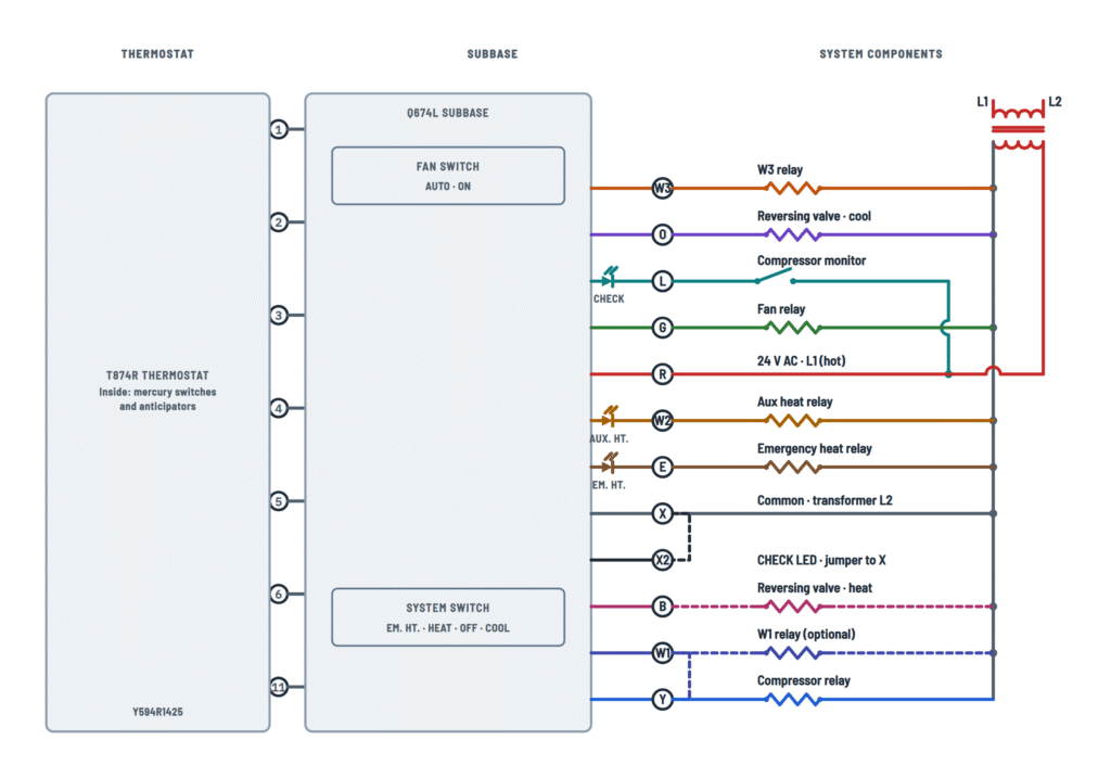
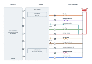
Package Y594R1425: T874R1616 thermostat on the Q674L1587 subbase.
Data
- LEDs: AUX. HT., EM. HT. and CHECK
- Universal model (SUPER TRADELINE): valve on O or B
- Factory jumpers W1–Y and X–X2
- Fixed heat anticipation
Mounting
Level the subbase with a spirit level: if it is off level, the (mercury) thermostat drifts from the setpoint. One wire per terminal except factory jumpers, and plug the cable hole to stop drafts.
Caution
Turn the power off before wiring. The thermostat contains mercury: recycle it when replaced.
Model
Package Y594R1615: T874R1822 thermostat on the Q674L1710 subbase.
Data
- LEDs: AUX. HT., EM. HT. and CHECK
- Reversing valve on O (cooling) or B (heating)
- For units without a W2–E jumper
- Fixed heat anticipation
Mounting
Level the subbase with a spirit level: if it is off level, the (mercury) thermostat drifts from the setpoint. One wire per terminal except factory jumpers, and plug the cable hole to stop drafts.
Caution
Turn the power off before wiring. The thermostat contains mercury: recycle it when replaced.
Model
Package Y594R1797: T874R1988 thermostat on the Q674L1868 subbase.
Data
- LEDs: AUX. HT. and EM. HT.
- Reversing valve on O (cooling) or B (heating)
- W3 on some models only; X may be labeled C/X
Mounting
Level the subbase with a spirit level: if it is off level, the (mercury) thermostat drifts from the setpoint. One wire per terminal except factory jumpers, and plug the cable hole to stop drafts.
Caution
Turn the power off before wiring. The thermostat contains mercury: recycle it when replaced.
What it does
Brings the transformer hot side to the thermostat, which sends it back through G, Y, O, W… as needed.
How to connect it
18 AWG color-coded thermostat cable; one wire per terminal, with the screw firmly tightened.
What it does
The unit's monitor closes its contact between R and L when it detects a fault; the thermostat lights the LED as a warning.
What it does
The unit's monitor closes its contact between R and L when it detects a fault; the thermostat lights the LED as a warning.
Data
The EM. HT. LED also signals a compressor fault.
What it does
The unit's monitor closes its contact between R and L when it detects a fault; the thermostat lights the LED as a warning.
Check
The exact meaning of the CHECK LED is given in the equipment manual.
What it does
Completes the 24 V circuit: the equipment coils return to L2 and the thermostat LEDs light against this terminal.
What it does
Completes the 24 V circuit: the equipment coils return to L2 and the thermostat LEDs light against this terminal.
Name
On some models this terminal is labeled C/X.
What it does
The CHECK LED has isolated terminals (L and X2) to suit any system. With the factory X–X2 jumper, the LED lights when the unit powers L.
What it does
With the FAN switch on ON the blower runs continuously; on AUTO the thermostat runs it with heating or cooling.
Data
In emergency heat (EM. HT.) the fan runs automatically.
What it does
On a heat pump, the compressor provides cooling and the first heating stage; the reversing valve sets the mode.
Data
In the typical diagram the contactor goes through the unit's safeties: low ambient cutout (LACO) and high pressure (CHP).
Tip
Some units wait about 5 minutes before restarting the compressor: it is a protection, not a fault. Do not run cooling when it is below 50 °F (10 °C) outdoors.
What it does
On a heat pump, the compressor provides cooling and the first heating stage; the reversing valve sets the mode.
W1–Y jumper
Factory-installed: remove it only when a W1 relay is used.
Tip
Some units wait about 5 minutes before restarting the compressor: it is a protection, not a fault. Do not run cooling when it is below 50 °F (10 °C) outdoors.
What it does
On a heat pump, the compressor provides cooling and the first heating stage; the reversing valve sets the mode.
Tip
Some units wait about 5 minutes before restarting the compressor: it is a protection, not a fault. Do not run cooling when it is below 50 °F (10 °C) outdoors.
What it does
W1 comes tied to Y by a factory jumper, so heat stage 1 starts the compressor. If the unit has a W1 relay, remove the jumper and wire the relay between W1 and common.
Check
Remove the jumper only if the unit's diagram calls for a W1 relay.
What it does
Energized with the SYSTEM switch on COOL so the heat pump cools.
Data
This model is for valves energized in cooling.
Check
If the unit heats on a call for cooling, the valve is on the wrong terminal or the model does not match the unit.
What it does
Energized with the SYSTEM switch on COOL so the heat pump cools.
How to connect it
The valve goes on O if the unit energizes it in cooling, or on B if in heating; never on both.
Check
If the unit heats on a call for cooling, the valve is on the wrong terminal or the model does not match the unit.
What it does
In this model's typical diagram B does not go to the unit: the reversing valve connects to O.
Check
If the old thermostat had a wire on B, check the unit's diagram: on other brands B is the common.
How to connect it
Connect the reversing valve to B only if the unit energizes it in heating; if it is energized in cooling, it goes on O.
What it does
In the typical diagram, B drives a unit "B" relay; the cooling valve stays on O.
Check
The "B" relay's function is set by the unit: follow its diagram.
What it does
It is the second heat stage: it comes on about 1 °F (0.6 °C) after the first if the compressor cannot keep up. The AUX. HT. LED lights while it runs.
Data
In the typical diagram, W2 drives the first heat strip time-delay relay.
Caution
Do not jumper the heating relay coil terminals with the thermostat connected: it burns out the heat anticipator.
What it does
It is the second heat stage: it comes on about 1 °F (0.6 °C) after the first if the compressor cannot keep up. The AUX. HT. LED lights while it runs.
Data
W2 powers the first time-delay relay and, through it, the next stages, which come on according to the unit's outdoor thermostats.
Caution
Do not jumper the heating relay coil terminals with the thermostat connected: it burns out the heat anticipator.
What it does
It is the second heat stage: it comes on about 1 °F (0.6 °C) after the first if the compressor cannot keep up. The AUX. HT. LED lights while it runs.
Caution
Do not jumper the heating relay coil terminals with the thermostat connected: it burns out the heat anticipator.
What it does
It is the second heat stage: it comes on about 1 °F (0.6 °C) after the first if the compressor cannot keep up. The AUX. HT. LED lights while it runs.
Data
For units without a W2–E jumper.
Caution
Do not jumper the heating relay coil terminals with the thermostat connected: it burns out the heat anticipator.
What it does
Feeds heat strip stages 2 and 3 through time-delay relays: they come on after stage 1 and only when their outdoor thermostat allows it or in emergency heat.
What it does
Drives the unit's W3 relay, for more auxiliary heat.
What it does
Drives a second auxiliary heat relay.
Data
The W3 terminal exists on some models only.
What it does
With the switch on EM. HT. the compressor stays off and, on a call for heat, the emergency relay is energized. The EM. HT. LED stays on while the switch is in that position.
Test
Switch on EM. HT. and setpoint about 10 °F (6 °C) above room temperature: the heat strips should come on.
What it does
With the switch on EM. HT. the compressor stays off and, on a call for heat, the emergency relay is energized. The EM. HT. LED stays on while the switch is in that position.
Data
This model is for units where W2 and E are not jumpered.
Test
Switch on EM. HT. and setpoint about 10 °F (6 °C) above room temperature: the heat strips should come on.
York replacements
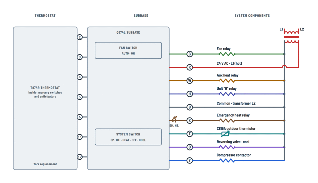
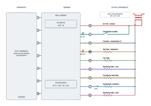
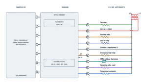
T874R1871, 1913, 1889 and 1905: common on B, emergency heat on X and outdoor thermistor on T.
Terminals and components · 10
- R · 24 V
- Common
- Fan
- Compressor
- Reversing
- Aux heat
- Emergency
- H relay
- Thermistor
Model
All four packages are wired the same; they differ in the York model they replace and the color.
Data
- LED: EM. HT. (red), between B and X
- Reversing valve energized in cooling (O)
- Y594R1698 includes the C815A1054 outdoor thermistor
- Y594R1698 and Y594R1706: Premier White color
Packages
Package Thermostat / subbase Replaces York Y594R1664 T874R1871 / Q674L1736 2TH11702224 Y594R1706 T874R1913 / Q674L1777 2TH11702224 Y594R1672 T874R1889 / Q674L1736 2TH11702324, 6TH11702224 Y594R1698 T874R1905 / Q674L1777 2TH11702324, 6TH11702224 Mounting
Level the subbase with a spirit level: if it is off level, the (mercury) thermostat drifts from the setpoint. One wire per terminal except factory jumpers, and plug the cable hole to stop drafts.
Caution
Turn the power off before wiring. The thermostat contains mercury: recycle it when replaced.
What it does
Brings the transformer hot side to the thermostat, which sends it back through G, Y, O, W… as needed.
How to connect it
18 AWG color-coded thermostat cable; one wire per terminal, with the screw firmly tightened.
What it does
Completes the 24 V circuit: the equipment coils return to L2 and the thermostat LEDs light against this terminal.
Caution
On these models the common is B, not X or C. On other thermostats B may be the reversing valve: do not copy another unit's wiring.
What it does
With the FAN switch on ON the blower runs continuously; on AUTO the thermostat runs it with heating or cooling.
Data
In emergency heat (EM. HT.) the fan runs automatically.
What it does
Energizes the unit's auxiliary heat relay to add the heat strips when the heat pump alone cannot keep up.
Caution
Do not jumper the heating relay coil terminals with the thermostat connected: it burns out the heat anticipator.
How to connect it
Between H and common (B), as on the original York thermostat.
Check
The diagram only names it "H" relay: confirm its function in the unit's diagram.
What it does
With the switch on EM. HT. the compressor stays off and, on a call for heat, the emergency relay is energized. The EM. HT. LED stays on while the switch is in that position.
Test
Switch on EM. HT. and setpoint about 10 °F (6 °C) above room temperature: the heat strips should come on.
What it does
Measures the outdoor temperature; the thermostat adjusts its operation to it (outdoor reset).
How to connect it
Install it outdoors, in the shade, and wire it between T and common.
Data
The diagram shows the C815A1039; the Y594R1698 package includes the C815A1054. Use the one the unit calls for.
What it does
Energized with the SYSTEM switch on COOL so the heat pump cools.
Data
This model is for valves energized in cooling.
Check
If the unit heats on a call for cooling, the valve is on the wrong terminal or the model does not match the unit.
What it does
On a heat pump, the compressor provides cooling and the first heating stage; the reversing valve sets the mode.
Tip
Some units wait about 5 minutes before restarting the compressor: it is a protection, not a fault. Do not run cooling when it is below 50 °F (10 °C) outdoors.
GE / Trane replacement
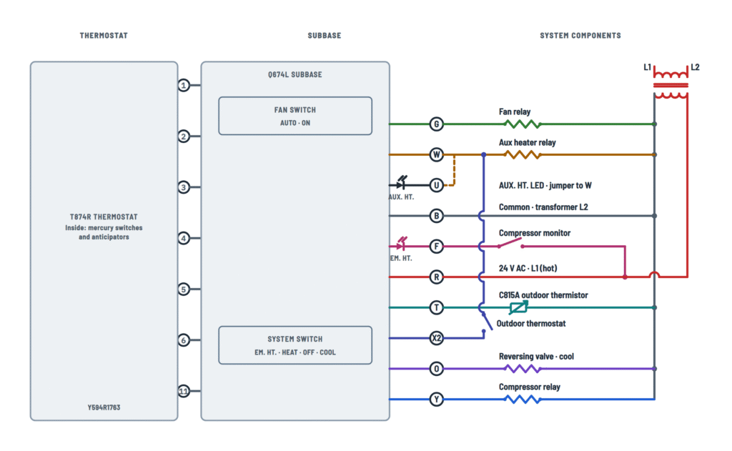
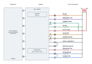
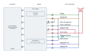
T874R1954: common on B, monitor on F, outdoor thermostat on X2 and thermistor on T.
Terminals and components · 11
- R · 24 V
- Common
- Fan
- Compressor
- Reversing
- Aux heat
- Outdoor thermostat
- Monitor
- Thermistor
- Jumper
Model
Package Y594R1763: T874R1954 thermostat on the Q674L1827 subbase. Replaces GE AY28X078 and AY28X139, Trane Baystat 139, 239 and 240, and Honeywell Y594R1136.
Data
- LEDs: AUX. HT. and EM. HT. (also signals compressor fault)
- Requires the C815A outdoor thermistor
- Reversing valve energized in cooling (O)
- Fixed stage 1 anticipation; none on stage 2
Mounting
Level the subbase with a spirit level: if it is off level, the (mercury) thermostat drifts from the setpoint. One wire per terminal except factory jumpers, and plug the cable hole to stop drafts.
Caution
Turn the power off before wiring. The thermostat contains mercury: recycle it when replaced.
What it does
Brings the transformer hot side to the thermostat, which sends it back through G, Y, O, W… as needed.
How to connect it
18 AWG color-coded thermostat cable; one wire per terminal, with the screw firmly tightened.
What it does
The unit's monitor closes its contact between R and F when it detects a fault; the thermostat lights the LED as a warning.
Data
The EM. HT. LED also signals a compressor fault.
What it does
Completes the 24 V circuit: the equipment coils return to L2 and the thermostat LEDs light against this terminal.
Caution
On these models the common is B, not X or C. On other thermostats B may be the reversing valve: do not copy another unit's wiring.
What it does
With the FAN switch on ON the blower runs continuously; on AUTO the thermostat runs it with heating or cooling.
Data
In emergency heat (EM. HT.) the fan runs automatically.
What it does
With the W–U jumper, the AUX. HT. LED lights when the auxiliary heat relay is energized.
Check
The jumper is field-removable, but no reason is given: leave it unless the unit's diagram says otherwise.
What it does
Energizes the auxiliary heater relay to add the heat strips when the heat pump alone cannot keep up.
Caution
Do not jumper the heating relay coil terminals with the thermostat connected: it burns out the heat anticipator.
What it does
With the outdoor thermostat contact closed, the X2 output also energizes the auxiliary heater relay, adding heat strips when it is cold outside.
How to connect it
X2 goes to one side of the contact; the other side joins the W wire at the unit.
What it does
Measures the outdoor temperature; the thermostat adjusts its operation to it (outdoor reset).
How to connect it
Install it outdoors, in the shade, and wire it between T and common.
Data
This model requires the C815A outdoor thermistor for outdoor reset.
What it does
Energized with the SYSTEM switch on COOL so the heat pump cools.
Data
This model is for valves energized in cooling.
Check
If the unit heats on a call for cooling, the valve is on the wrong terminal or the model does not match the unit.
What it does
On a heat pump, the compressor provides cooling and the first heating stage; the reversing valve sets the mode.
Tip
Some units wait about 5 minutes before restarting the compressor: it is a protection, not a fault. Do not run cooling when it is below 50 °F (10 °C) outdoors.
About This Diagram
These diagrams are redrawn from pages 1 and 4–7 of the Honeywell T874R Thermostat manual, and we offer them completely free and in English. We have also categorized it in the Thermostats (HVAC & Water Heating) section on Diagramverse, and it has been rated by 1 user with an average rating of 5.0. If you have any specific questions about the Honeywell T874R Thermostat Wiring Diagram, we suggest checking the Frequently Asked Questions (FAQs) section.
Printable Honeywell T874R Wiring Diagrams
Wiring Instructions
Before you start
The Honeywell T874R is a mercury-switch thermostat for heat pumps with two heat stages and one cool stage. It mounts on a Q674L subbase, and all wiring lands on the subbase. First match your equipment to a diagram tab. Use the Honeywell tab and select the variant printed on your thermostat (T874R1152, T874R1475, T874R1616, T874R1822 or T874R1988). Use the York tab for the York replacement kits. Use the GE / Trane tab for kit Y594R1763 (T874R1954), which replaces GE AY28X078 and AY28X139, Trane Baystat 139, 239 and 240, and Honeywell Y594R1136.
- Tools: small screwdriver, wire stripper, bubble level, drill with a 3/16 in bit and anchors (wall mount), a multimeter, and an AC ammeter if your model has an adjustable anticipator.
- Wire: color-coded 18 AWG thermostat cable, preferably solid. If you use stranded 18 AWG, use no more than 10 conductors. Never use wire heavier than 18 AWG.
- Power: turn off the heat pump and air handler at their disconnects and confirm with a meter that there is no voltage between R and common.
- Who should install it: this job is meant for a trained service technician. Line-voltage work on the transformer, the outdoor disconnect or the heat strips follows local code and may need a licensed electrician or a permit.
Mount the thermostat about 5 ft above the floor on an inside wall with good air circulation. Keep it out of drafts, sun, supply-air streams and dead spots behind doors.
Step-by-step wiring
- Label each old wire with the terminal letter it came from before you disconnect it. If you are replacing an older T872R or T874R, the letters may change. For example, an old W often moves to W2. Follow the equivalents for your exact kit.
- Pull the cable through the subbase opening. On a vertical electrical box, use the 193121A adapter ring. Start the mounting screws, level the subbase with a bubble level and then tighten. The thermostat is calibrated for a perfectly level base.
- Strip 5/16 in (8 mm) for straight insertion or 7/16 in (11 mm) to wrap the wire around the screw. Put only one wire under each terminal. The only exception is a factory jumper with spade terminals.
- Connect R to the hot side (L1) of the 24 to 30 V AC transformer. Then connect the common: X on the Honeywell tab, B on the York and GE / Trane tabs.
- Connect G to the blower relay and Y to the compressor contactor or relay.
- Connect the reversing valve. Use O if the valve is energized in cooling, or B if it is energized in heating. Never use both. On the T874R1152, B stays unconnected at the unit. On the T874R1988, B goes to the unit's "B" relay.
- Connect the auxiliary heat: W2 and W3 on the Honeywell tab, W on the York and GE / Trane tabs. Then connect emergency heat: E on Honeywell, X on York. On the GE / Trane tab, the outdoor thermostat runs from X2 to the W relay. Leave the W–U jumper in place so the AUX. HT. LED works.
- Connect the monitor terminal, L (Honeywell) or F (GE / Trane), to the unit's fault contact if the unit has one. On York, connect H to the unit's "H" relay.
- On the T874R1616, leave the X–X2 factory jumper alone. Remove the W1–Y jumper only if you wire a separate W1 relay.
- If the system includes a C815A outdoor thermistor, connect it between T and common. It must always stay connected.
- Tighten every screw firmly. Push the excess wire back into the wall and seal the hole with nonflammable insulation so drafts don't affect the reading.
- Remove the polystyrene shipping insert from the thermostat. Check that the spring fingers on the back are not bent flat. Hook the top tabs into the subbase and snug the two captive screws without overtightening them.
Testing and start-up
Restore power. Measure 24 to 30 V AC between R and common.
- Heat: set the system switch to HEAT and the lever about 10 °F above room temperature. Both stages and the fan should start. Set it 10 °F below room temperature and they should stop. Many heat pumps wait 5 minutes before restarting the compressor, which is normal.
- Cool: set the system switch to COOL and the lever 10 °F below room temperature. The compressor and fan should run. Do not test cooling when it is below 50 °F outdoors.
- Emergency heat: on EM. HT., the EM. HT. LED lights, the compressor stays off and the heat strips cycle with the lever.
- Fan: with the system switch on OFF and the fan switch on ON, the blower runs continuously. Make sure each slide switch sits in its detent.
- Anticipator: this applies only to models with an adjustable stage 2. With the thermostat off the base and power on, put an AC ammeter between W2 and R, select HEAT and read after 1 minute. Set the anticipator to that current. If the system cycles too fast, raise the setting no more than half a division at a time. Aim for 2.5 to 3 cycles per hour.
Safety notes
- This is a 24 to 30 V AC control circuit. Never connect it to 120/240 V. The subbase contacts are rated 2.5 A at 30 V AC (7.5 A inrush).
- Never jumper the terminals of a relay coil or gas valve coil, not even for a moment. It burns out the anticipator.
- The outdoor unit needs a disconnect within sight. Every power supply needs a disconnect and overload protection.
- The thermostat contains mercury in a sealed tube. Recycle the new and the old thermostat through your local waste authority. Never put them in the trash.
Troubleshooting
| Symptom | Probable Cause | What to Check |
|---|---|---|
| Nothing works and no LED ever lights | No 24 V supply, or the common is not connected | Measure between R and common (X on Honeywell, B on York and GE / Trane). You should read 24 to 30 V AC. If not, check the transformer, its fuse or breaker, and the R and common wires at both ends. |
| It blows warm air in COOL and cold air in HEAT | Reversing valve on the wrong terminal (O instead of B, or the other way around) | Find out whether the unit's valve is energized in cooling (use O) or in heating (use B). Move the wire so only one of the two is used. |
| The heat pump turns on and off very often | Stage 2 anticipator set too low for the relay current | Measure the current between W2 and R after 1 minute in HEAT. Set the anticipator to that value, then raise it half a division at a time until you get 2.5 to 3 cycles per hour. |
| The thermostat stopped heating right after someone tested the unit | A relay coil or gas valve coil was jumpered, which burned the anticipator | Inspect the anticipator for damage and replace the thermostat if it is open. Never jumper coil terminals during tests. |
| Cooling or heating calls but the compressor never starts | Y wire loose or on the wrong terminal, or a bad contactor | Wait 5 minutes for the anti-short-cycle timer. Then measure between Y and common. If you read 24 V AC there, the fault is at the contactor or relay. If not, check the Y wire. |
| A separate W1 relay never energizes on a T874R1616 | The factory W1–Y jumper is still installed | Remove the W1–Y jumper when you use a separate W1 relay. Then confirm 24 V AC between W1 and common during a heat call. |
| The EM. HT. or CHECK LED is on although EM. HT. was not selected | The unit's fault contact on L (or F) is reporting a compressor fault, or the monitor wire is on the wrong terminal | Check the compressor and the unit's fault device. Confirm that L or F goes only to the unit's monitor contact, not to a terminal that is always powered. |
| Backup heat works but the AUX. HT. LED never lights (GE / Trane) | The W–U jumper was removed | Reinstall the jumper between W and U on the subbase. |
| The room drifts several degrees below the setpoint in cold weather (York, GE / Trane) | The C815A outdoor thermistor is disconnected or out of tolerance | Disconnect the T wire and measure the thermistor. Expect 400 Ω ±10 % at 77 °F. Replace it if the reading differs from the curve by more than 15 %. |
| The temperature never matches the setting | The subbase is not level | Put a bubble level on the subbase, loosen the screws, level it and retighten. |
| It works intermittently or ignores some modes | Spring fingers bent flat, a loose screw, two wires under one terminal, or a slide switch not seated in its detent | Check the fingers on the back of the thermostat and tighten each terminal. Use one wire per screw and slide each switch fully onto its mark. |