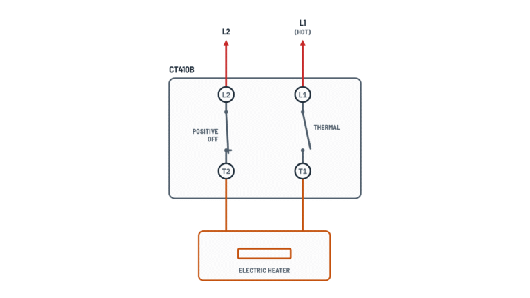
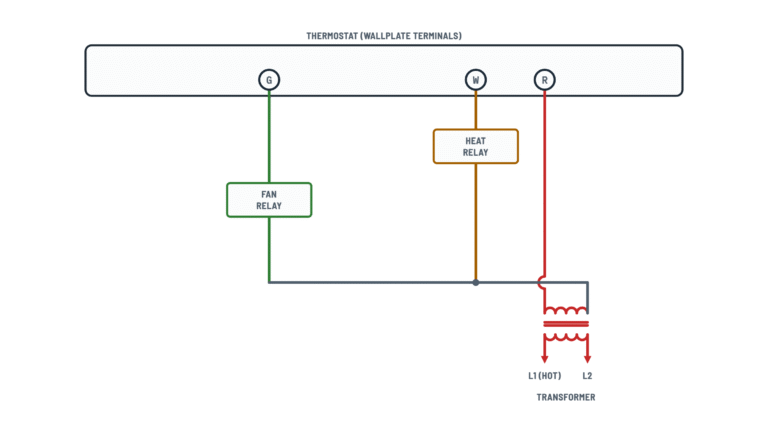
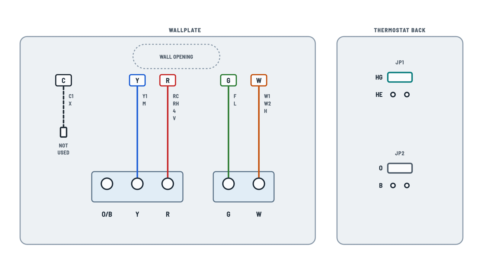
Honeywell RTH111B Thermostat Wiring Diagram
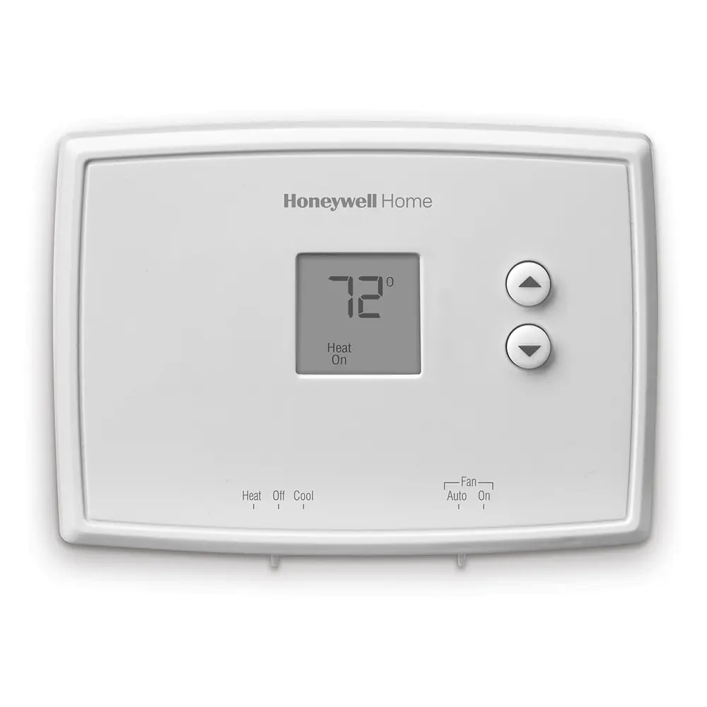
RTH111B wallplate
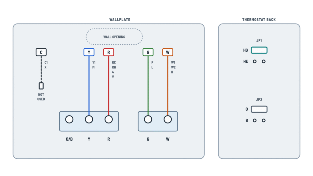
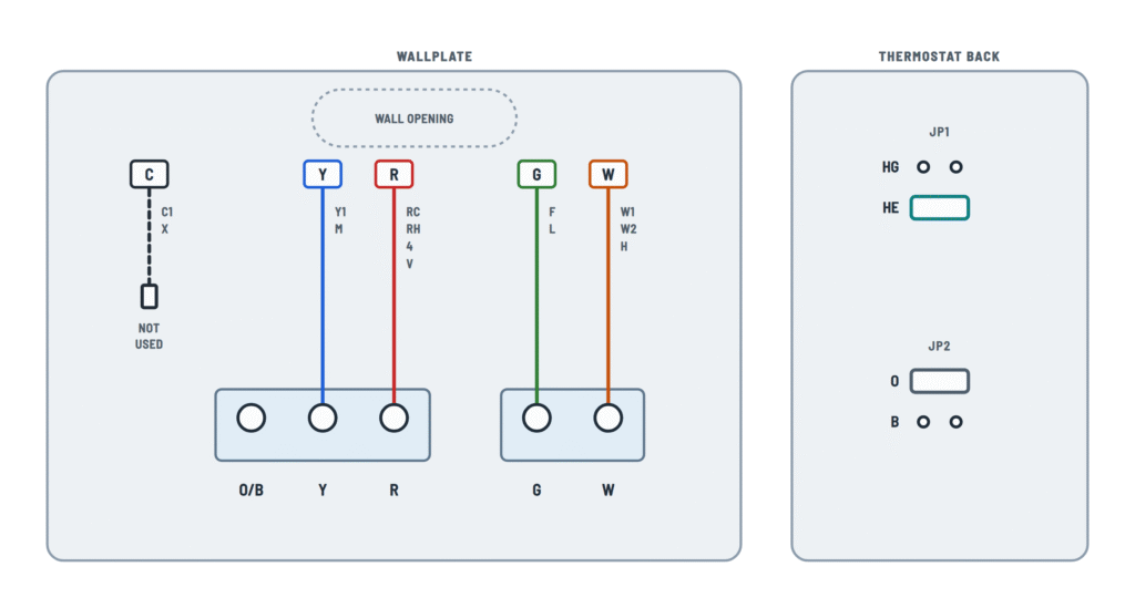
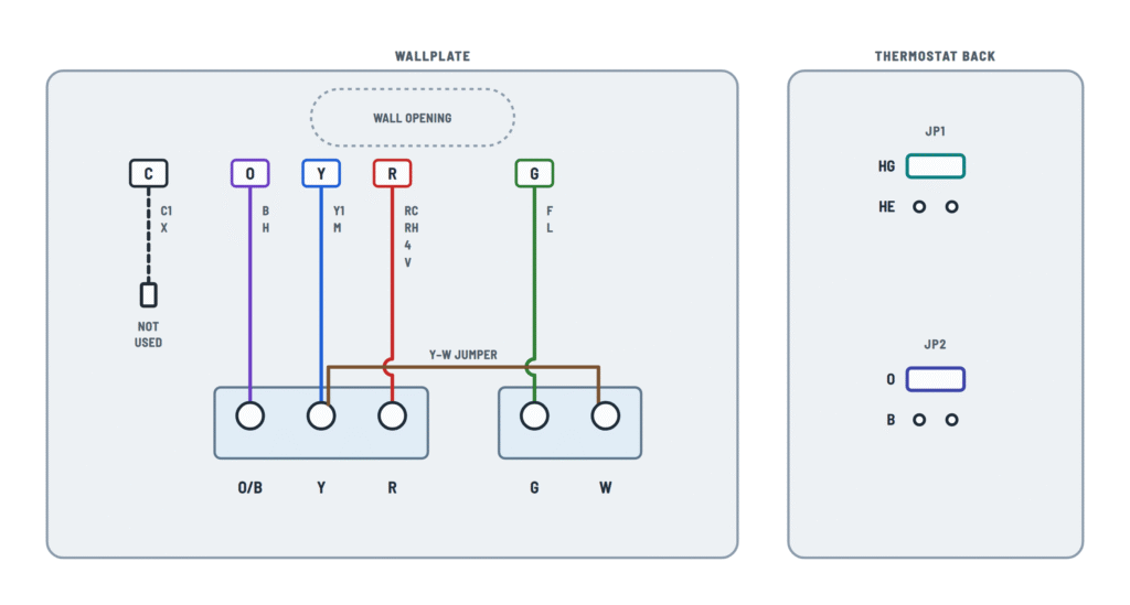
Wallplate terminals, the old thermostat's wire letters and jumpers JP1 and JP2.
Terminals and components · 7
- R (24 V)
- Compressor
- Fan
- Heating
- Reversing valve
- Y–W jumper
- JP1
- JP2
- Not used
What it does
It is the supply wire the thermostat connects to Y, G or W to turn on each function.
Caution
If the old thermostat had any two of these wires (R, RC, RH, 4 and V), this thermostat cannot be used.
What it does
Turns on the air conditioner. On heat-only systems the terminal stays empty.
Compressor protection
With function 3 on (factory setting), the compressor waits 5 minutes before restarting; meanwhile Cool On or Heat On flashes.
What it does
Starts the heat pump compressor, in both cooling and heating.
Compressor protection
With function 3 on (factory setting), the compressor waits 5 minutes before restarting; meanwhile Cool On or Heat On flashes.
What it does
Moves the air on forced-air systems. If you connect a wire here, set jumper JP1.
No G wire
Hot water or millivolt systems usually have no G wire: leave the terminal empty.
What it does
Gas, oil or electric furnace, hot water boiler or millivolt system: one stage only.
Cycles per hour
Set function 2 to match the system: 2 steam or gravity, 3 hot water or high-efficiency furnace, 4–5 gas or oil, 6 electric.
What it does
Energizes the reversing valve. Jumper JP2 tells whether the wire is O or B.
If you have both O and B
Use only the O wire; tape the B wire.
What it does
This way the heat call also starts the compressor: the heat pump heats with the compressor and reversing valve.
What to do
Wrap the bare end of each unused wire (C, C1, X, or any that were loose) with electrical tape so it can't touch other wires.
Batteries
The thermostat runs on two AAA batteries, on its back.
What it means
O/B is for the heat pump reversing valve.
When it goes on HG
Gas or oil furnace: leave it in the factory position.
Wrong setting
If cold air comes out of the vents when heating starts, the fan is starting too early: check JP1.
When it goes on HE
Electric furnace: the thermostat turns on the fan together with the heat.
Check
The manual only lists HG (gas or oil) and HE (electric). For a heat pump, check with the equipment manufacturer which position applies.
How to set it
- O wire on O/B: leave JP2 on O.
- B wire on O/B: move JP2 to B.
Wrong setting
The heat pump runs in reverse: it cools in Heat mode and heats in Cool mode.
About This Diagram
This diagram is redrawn from pages 5–8 of the Honeywell RTH111B Thermostat manual, and we offer it completely free and in English. We have also categorized it in the Thermostats (HVAC & Water Heating) section on Diagramverse, and it has been rated by 1 user with an average rating of 5.0. If you have any specific questions about the Honeywell RTH111B Thermostat Wiring Diagram, we suggest checking the Frequently Asked Questions (FAQs) section.
Printable Honeywell RTH111B Wiring Diagrams
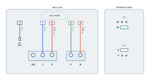
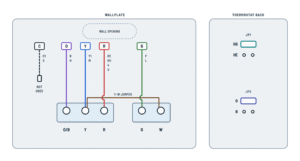
Wiring Instructions
Before you start
The Honeywell RTH111B is a single-stage thermostat that runs on two AAA batteries. It works on 24 V systems and 750 mV millivolt systems. Use the variant selector to pick your installation. Choose Gas or oil for a gas or oil furnace or boiler, Electric furnace for any type of electric heat, and Heat pump, no aux heat only if your heat pump has no backup or emergency heat. Your system is multistage or has aux heat if the old thermostat has wires on terminals marked W2, Aux, E or Y2, or has an emergency heat setting. In that case, this thermostat is not suitable. It also cannot control 120/240 V line-voltage heaters.
- Tools: small flat and Phillips screwdrivers, a drill with a 3/16 in. bit for drywall or a 3/32 in. bit for plaster, a level, a wire stripper and a multimeter.
- Materials: the supplied wire labels, screws and anchors, two AAA alkaline batteries, electrical tape, and a short piece of thermostat wire if you need the Y–W jumper.
- Wire: reuse the existing thermostat cable. The sources do not give a gauge. Solid 18 AWG thermostat cable is standard practice for 24 V control wiring.
Turn off power at the circuit breaker or at the heating/cooling system's power switch. Homeowners normally replace a low-voltage thermostat themselves. Call a licensed HVAC technician in these cases:
- You find heavy line-voltage wires joined with wire nuts behind the old thermostat.
- You can't identify your system type.
- The job needs work inside the furnace or air handler.
Permit rules vary by area, so check them locally.
Step-by-step wiring
- Remove the old thermostat body but leave its wallplate and wires attached. Take a photo of the terminals before touching anything.
- As you disconnect each wire, label it with the letter of the terminal it was on. If the old unit has a sealed tube of mercury, do not put it in household trash. Take it to a thermostat recycling program.
- Pull the new wallplate off the bottom of the thermostat. Feed the wires through it, level it and fix it to the wall with the included anchors and screws. Seal the wall opening so drafts don't affect the reading.
- Connect the power wire to R. Your old thermostat may have labeled it R, RC, RH, 4 or V. Only one of them goes to R.
- Connect the cooling wire (Y, Y1 or M) to Y and the fan wire (G, F or L) to G. Skip any terminal you have no wire for, such as Y on a heat-only system.
- Gas or oil and Electric furnace: connect the heating wire (W, W1, W2 or H) to W and leave O/B empty. If your old wiring has a B wire, do not connect it. Tape its bare end.
- Heat pump, no aux heat: connect the O or B wire to O/B, never both. No system wire goes to W. Instead, add a short piece of wire as the Y – W jumper.
- Wrap the bare ends of any C, C1 or X wires with electrical tape and fold them back into the wall. The thermostat does not use them.
- Make sure each conductor is fully under its screw with no stray strands. Tighten the screws and give each wire a gentle tug.
- Set JP1. Leave it in the factory HG position for gas or oil heat. Move it to HE (Electric or Heat Pump) for an electric furnace or a heat pump, so the thermostat runs the fan on a call for heat through G.
- On a heat pump, set JP2 to match the valve wire: O (factory) for an O wire, B for a B wire.
- Install two AAA alkaline batteries, checking polarity. Then snap the thermostat onto the wallplate.
Testing and start-up
Restore power at the breaker or system switch. Then press and hold both the up and down buttons for about 5 seconds to enter setup.
- Function 5 (heating cycle rate):
- 5: gas or oil furnace under 90% efficiency
- 6: any electric heat
- 3: heat pump, hot water, or gas furnace over 90% efficiency
- 2: steam or gravity heat
- Function 14: 0 for °F, 1 for °C.
- Function 15: compressor protection, 1 (on) recommended.
To move to the next function, press up and down together for one second. The menu saves and exits after 60 seconds without a key press.
Then test each mode:
- Heat: set the System switch to Heat and raise the setpoint above room temperature. "Heat On" should appear and heat should start.
- Cool: set the System switch to Cool and lower the setpoint. "Cool On" may flash for up to 5 minutes while compressor protection times out before the compressor starts.
- Fan: set the Fan switch to On. The blower should run continuously.
- Heat pump: confirm that Heat gives warm air and Cool gives cool air.
If nothing responds, remove the thermostat and measure AC voltage between the R wire and the taped C wire, if one is present. You should read 20–30 VAC.
Safety notes
- The terminals are rated 20–30 VAC. The current limits are:
- W and Y: 1.0 A
- G, O and B: 0.5 A
- W on a millivolt power-pile system: 750 mV DC, 100 mA
Never connect the thermostat to 120/240 V.
- Keep the taped C wire away from R and the other terminals. A short between R and C can blow the low-voltage fuse on the equipment's control board.
- Set the System switch to Off before you remove the batteries. Otherwise the system can stay on.
- To avoid compressor damage, do not run the air conditioner when the outdoor temperature is below 50 °F (10 °C).
Troubleshooting
| Symptom | Probable Cause | What to Check |
|---|---|---|
| The screen is blank after installation | Batteries are missing, dead, reversed or not alkaline | Pull the thermostat off the wallplate and fit two fresh AAA alkaline batteries with the polarity marked on the back |
| The display works but nothing turns on in any mode | No 24 V on R: breaker off, system power switch off or furnace door not closed | Measure AC voltage between R and the taped C wire at the wall; you should read 20–30 VAC. If it reads zero, check the breaker, the power switch and that the furnace door is fully closed |
| The furnace went completely dead during or right after the swap | The bare C, C1 or X wire touched R and blew the low-voltage fuse | Turn off power and check the small fuse on the furnace or air handler control board. Replace it with the same rating and re-tape the unused wire ends |
| The heat pump blows cold air in Heat and warm air in Cool | JP2 does not match the valve wire | Set JP2 to O if the wire on O/B is O, or to B if it is B |
| The heat pump cools fine but does nothing in Heat | The Y – W jumper is missing or loose | Install a short piece of wire between Y and W and tighten both screws |
| With electric heat, the heat comes on but the blower stays off | JP1 left in the factory HG position, or the G wire is loose | Move JP1 to HE and confirm the G, F or L wire is secure on G |
| The fan won't run in Fan On or during cooling | The fan wire is on the wrong terminal or not connected | Check that the G, F or L wire is on G; with Fan set to On, the blower should start |
| The heat won't shut off, or the system acts strangely on a non-heat-pump system | A B wire was connected to O/B (on some older systems B is a common), or the W wire touches R | On conventional systems, leave O/B empty and tape any B wire; inspect W for stray strands touching R |
| "Cool On" flashes and the compressor doesn't start for several minutes | Compressor protection delay is running, which is normal | Wait 5 minutes. If it never starts afterward, check the Y wire connection |
| The heat cycles on and off too often or the room temperature swings widely | Function 5 heating cycle rate does not match the system | In setup, set Function 5 to 5 (standard gas/oil), 6 (electric), 3 (heat pump, hot water, high-efficiency) or 2 (steam/gravity) |